Metallographic Sample Preparation and Examination of Brazed Heat Exchangers
Sample Preparation – Orientation
The heat exchanger chosen for the purpose is a NOCOLOK Flux brazed radiator. To provide some orientation as to where the metallographic sections will be taken from, Figure 1 shows the water-side header area (top) and part of the finpack, sidesupport and header area.

Figure 1
In most metallographic investigations of brazed heat exchangers, the critical joints to examine are the tube-to-header joints and the fin-to-tube joints. For instance, a leak in a tube-to-header joint constitutes a failure. The fin-to-tube joint on the other hand, although not as critical as the tube-to-header joint, is the key area where heat transfer takes place. It is therefore necessary that the fin-to-tube joints are metallurgically bonded (i.e. brazed) for maximum heat transfer efficiency.
Sample Preparation – Sectioning
With a band saw, the radiator can be cut down through the center of the tubes (see Figure 2). This will keep the fins intact. If necessary, one can saw through the fins if the blade is kept as close to the outer tube wall as possible. That is the outer tube wall can be used to guide the saw blade. Otherwise, it is better to saw through the center of the tube where the inner walls will act as the guide.

Figure 2
Once the above sections have been obtained, the samples can be sawn longi-tudinally through the center of the tube and header as shown in Figure 2, right. The tube-to-header and tube-to-fin sections can then be cut. The size of the cut samples must fit inside a 30 mm or 40 mm mount. Note that it is the cut face that will be grinded and polished.
Grinding and Polishing
The following section shows what the sample actually looks like after each grinding and polishing step. The intention is to help the metallographer track the progress of grinding and polishing with the help of visual aids.
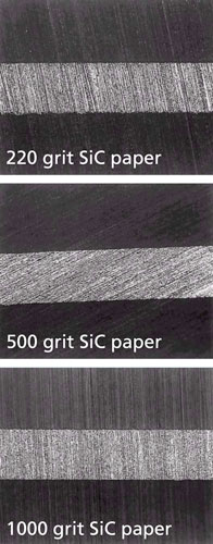
Figure 3 shows what a section of „unbrazed“ brazing sheet looks like under the microscope after wet grinding with 220, 500 and 1000 grit SiC paper. In each case, the sample is ground until all the grinding lines appear in the same direction, across the entire grinding face. It also helps that the grinding lines go in the direction of, or perpendicular to the area of interest. In this case, the grinding lines all run perpendicular to the braze sheet after 220 grit paper. After 500 grit paper (rotating the sample 90°), the grinding lines all run parallel to the tube and after 1000 grit, once more perpendicular to the braze sheet.
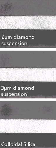
Figure 4 shows what the braze sheet looks like after each successive polishing step. After the 6 µm diamond suspension, the microstructure of the braze sheet becomes visible (more on microstructure later). At this stage, there are still a number of scratches. After the 3 µm diamond suspension, the micro-structure is clearer and there are less scratches. Only after the colloidal silica are all scratches removed. The 64x magnification in Figure 4 is too small to reveal fine micro-structural details after the colloidal silica polish, but what is evident is that the braze sheet is now highly polished and scratch free.

Figure 3

Figure 4

It’s good to know that a leak in the tube-to-header joint constitutes a failure. I recently bought some property with a few different heat exchangers. I will make sure to keep your article in mind while inspecting them!