Selective Pre-Fluxing with Adhesives – Fashion or Progress
Summary
Over the last 15 years, selective pre-fluxing – also called paint fluxing or binder-based fluxing – has evolved as an alternative method for applying flux powder in aluminium brazing industry. There are many activities to define process parameters of fluxing with adhesives.
The first part of this paper outlines key features of pre-fluxing. The methodology for measurements of physical characteristics of binders and paint flux mixtures are described. General rules for behaviour of flux paints in brazing process are discussed together with some examples of flux paint features.
In the second part a case study is shown to illustrate common challenges when brazing with flux paint. The last part of this paper provides a cost comparison as guidance for choosing the right fluxing method for two different cases, one being extremely negative and the second as a positive case.
3. Overview of Binders
| Group | Adhesion providing components | Co-solvents / dispersion agents (examples only) | Carriers / solvents |
|---|---|---|---|
| 1 | Polyurethane (aqueous polyurethane dispersion) | N-Methyl-2-pyrrolidon | water |
| 2 | Water-based acrylic | 3-Methoxy-3-methyl-1-butanol | water |
| 3 | Solvent-based acrylic | 1-Methoxy-2-propyl acetate and others | Preferably non-explosive and non-flammable organic solvents (e.g. esters of dicarboxylic acids) |
Table 1: Main groups of flux binders / flux paints.
One of the most important characteristic of a binder is the kinetics of binder removal. This property is measured by a method called Differential Thermal Analysis [DTA]. The specimen (binder or flux paint) is placed in a small crucible and heated with a preset rate. The device measures the change of weight of the specimen and heat emitted or absorbed by the sample. The test can be done in air or at a chosen gas atmosphere.
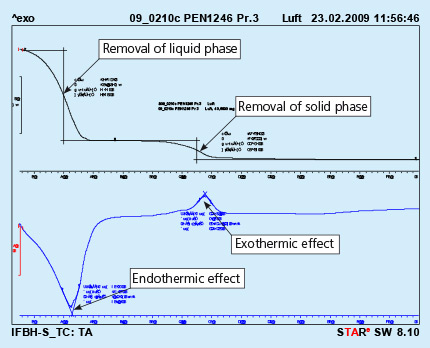
An example of the curves obtained in such device is shown in Fig. 1

Fig. 1: DTA curves obtained from solid flux paint sample. Test performed in air.
The upper curve represents lost of weight upon heating, and the lower curve represents thermal effects appearing in the heated sample. The endothermic effect is associated with evaporation of the sample and the exothermic effect is usually connected with burning of the sample.
It should be observed that the above curves represent a sample of liquid flux paint. The removal of the the liquid phase (carrier evaporation) takes place during curing of the painted part. This process is always done before putting the parts into the brazing line. For flux paints made with water as a carrier it is simple evaporation.
Removal of the solid phase (cured binder) takes place at much higher temperature then evaporation of the carrier. It usually happens in the brazing line – in the dryer and partially in the brazer. Kinetics of the solid phase removal is shown in Fig. 2. In this case the analyzed sample is prepared by painting a metal surface, curing the paint and careful scratching off the solid paint, which is then analyzed in DTA device.

Fig. 2: DTA curves obtained from liquid flux paint sample. Test performed in air.
As can be seen the end of the binder removal is in the temperature range of 450oC. The above presented curves show the removal of binder at a constant heating rate of the sample (in this case 10oC/min). In the brazing line the prefluxed parts firstly go through a dryer where the temperature for dry parts is usually in between 200oC to 250oC. The parts for a continuous brazing line usually stay in the dryer no longer than 10 minutes.
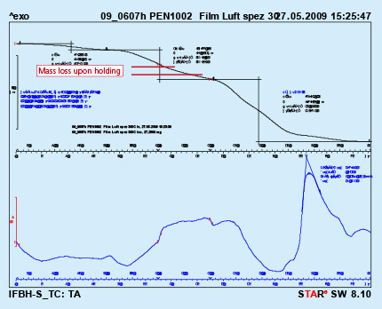
To simulate this condition, a dry flux paint sample was analyzed by DTA with a hold for 10 minutes at 300oC. As can be seen from Fig. 3, holding at constant temperature for a prolonged time does not lead to full removal of the binder. In the given case only about 36% of the binder was removed.

Fig. 3: DTA curves with holding time 10min. at 300oC Test performed in air.
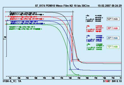
Different furnace design and different size of the brazed parts are responsible for different heating kinetics in the brazing lines. An influence of different heating rates on kinetics of binder removal is shown in Fig. 4.

Fig. 4: DTA curves with different heating rates Test performed in nitrogen.
The curves presented in Fig. 4 were obtained from analyzing a polyurethane binder heated in nitrogen atmosphere. It can be seen that only the middle temperature is moved to higher values with increased heating rate. The beginning and end of the debinding process do not depend on the heating rate.
Several examples of debinding temperatures for different type of binders are presented in table 2.
| Binder Type | Tested in Air | Tested in Nitrogen | ||||
| Middle temp. [°C] | End Temp. [°C] | Weight loss [%] | Middle temp. [°C] | End Temp. [°C] | Weight loss [%] | |
| Polyurethane Binder A | 355 | 530 | 99.7 | 370 | 460 | 99.6 |
| Polyurethane Binder B | 360 | 550 | 98.5 | 370 | 460 | 97.5 |
| Acrylic Binder C (water soluble) | 317, 382 | 450 | 87.2 | 220, 387 | 430 | 85.2 |
| Acrylic Binder D (high adhesion) | 267 | 420 | Not measured* | 385 | Not measured* | 27.5 |
| Acrylic resin Binder E | 275 | 400 | 86.9** | 370 | 450 | 89.3** |
| * DTA performed only on ready mixtures **Lower values due to some flux residue (sample obtained from ready mixture) |
||||||
Table 2: Examples of debinding temperatures for different types of binders.
Will be continued soon.
