Selective Pre-Fluxing with Adhesives – Fashion or Progress
Summary
Over the last 15 years, selective prefluxing – also called paint fluxing or binderbased fluxing – has evolved as an alternative method for applying flux powder in the aluminium brazing industry. There are many activities to define process parameters of fluxing with adhesives.
The first part of this paper outlines key features of prefluxing. The methodology for measurements of physical characteristics of binders and paint flux mixtures are described. General rules for behaviour of flux paints in brazing process are discussed together with some examples of flux paint features.
In the second part a case study is shown to illustrate common challenges when brazing with flux paint. The third and last part of this paper provides a cost comparison as guidance for choosing the right fluxing method for two different cases, one being extremely negative and the second as a positive case.
4. Flux Paint Risk Point
The fundamental condition for successful brazing is having a substrate surface which is well wetted by a molten filler alloy. Any binder as an organic compound contains carbon. This carbon must be removed before brazing, otherwise it will form a very thin deposit on the substrate surface preventing wetting by the molten filler alloy2. When the flux paint is deposited on open surface areas, like for example on the radiator headers, there is no issue to remove the binder by evaporation at higher temperature. However, when the flux paint is applied in enclosed spaces, like for example on inner surfaces of condenser manifolds, the removal of binder becomes challenging. Proper de-bindering conditions must allow the binder fumes to escape completely. Residual binder – like any other trace organic – carbonizes during the brazing cycle – causing surface discoloration and potentially poor brazing.
Fig. 5 shows a leak in the tube apex. The condenser manifold was made of two halves: cover and header. Only the cover part was prefluxed by immersion. Composition of the flux paint: flux ~ 30%; carrier (acetone) ~ 62%; binder (polymethyl methacrylate) ~ 12%.
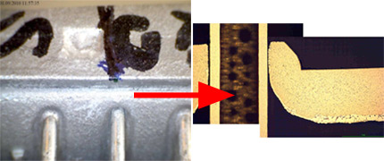
Fig. 5: Leak in tube to manifold joint in condenser with manifold half flux painted by immersion.
The gap size between the tube and manifold is in the range of 40µm, which is well within the maximum recommended tolerance.
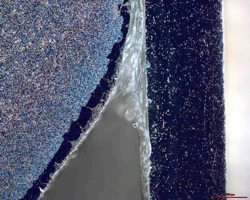
Fig. 6: Dark field image of the non brazed tube to manifold joint.
Dark field image of the non brazed joint showed that the gap is filled with transparent substance. Investigation by Scanning Electron Microscope revealed that the joint was completely filled with post braze flux residue.

Fig. 7: Mapping of potassium in the non brazed area of the joint.
The tube surface presented in Fig. 7 shows very uneven flux distribution. There are areas completely free of potassium (flux) and areas covered with a layer of flux. This would indicate that the tube surface was not completely wetted by flux upon application. Such “poisoning” of the surface can appear when it is contaminated with carbon. Though the overall level of carbon (as examined be SEM) is low, its distribution is uniform. The carbon most likely originated from binder traces. It seems that during debindering treatment the carbon got embedded into the aluminium oxide layer. Such a modified aluminium oxide layer is more difficult for the flux to remove.
5. Example of cost comparison calculation
The major reason behind the decision to introduce flux painting technology should be reduced overall cost of the manufacturing process. These should include:
- Media
- Maintenance
- Environment (cost of waste utilization)
- Raw material and consumables
- Labor
- Investment cost (depreciation)
In the following section we will present two examples of such calculations. It must be pointed out that the quoted numbers, though not far away from the values one can see in an aluminum brazing factory, may always differ from case to case. Thus the presented calculations should be considered only as a tool in which individual data needs to be fed, not as an indication which fluxing method is better.
Case A: Condensers
In the modified condenser production, the tube to fin joints are realized by tube precoating with NOCOLOK Si Flux3 – while the manifolds are prefluxed with a water based flux paint. This concept allows for complete elimination of the fluxer and the thermal degreaser from the brazing line. The dryer then acts as preheat and oven, where partial debindering takes place.
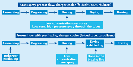
Fig. 8: Standard and modified process flow for condenser production.
Table 3 shows assumed input values like for example cost of electricity and the difference between the cost of standard process and modified one in the above listed categories. The whole calculation is done in an excel table where one can play with different input data which shows how sensitive the overall cost is to a change in a given parameter. In this case analyses showed that the most sensitive factor is the cost of the Sil Flux precoated tubes. Change of price in tube material by 10% can entirely reverse the final result.
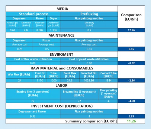
Table 3: Example calculation for standard and modified condenser manufacturing. Production level 200 pcs/hour.
Case B: Charger Coolers
Charge Air Coolers have one characteristic feature. Inside the tubes there are turbulators to make the flow of the hot compressed air more turbulent to increase the transfer of heat from the air to the tube walls. A condition to secure sufficient tube resistance to the inner pressure is to have all turbulators uniformly brazed to the inner tube surface. This requires fluxing of the tube’s internal surface. The most robust method is fluxing by immersion. This however produces higher post brazed flux residue levels and it is usually a bottle neck in the continuous production flow.
The other method is to apply a high pressure spray of flux slurry across the tubes. When combined with cross blow of high pressure air it secures proper inner fluxing even up to 900mm long tubes. This method does not slow down the production flow in a continuous line. For comparison the latter cross spray fluxing method is compared with prefluxing of turbulators. It should be remembered that wet fluxing is applied on tube to fin joints in both cases.
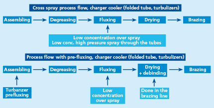
Fig. 9: Standard and modified process flow for charger coolers production.
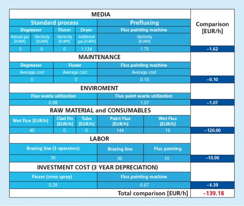
Table 4: Example calculation for standard and modified charge air cooler manufacturing. Production level 200 pcs/hour.
In this example there is no major change in the brazing line and as a matter of fact an additional entirely separate operation is added. This situation is somewhat improved when the flux painting process of the turbulators is incorporated into the tube making unit; however it eliminates only the negative effect of additional labor. The major cost is connected with consumption of flux paint. On average the cost of flux paint is about 20% higher than the cost of flux. Assuming liquid flux paint consumption of 4 grams per one turbulator and 50 grams of flux powder used on one charge air cooler fluxed by cross spray we will end up with such high difference in cost. In spite of this fact there are production lines which use the flux painting applied on turbulators.
6. Summary and conclusions
During recent years, the concept of prefluxing with binder flux/ paint flux has become quite popular as a method for fluxing. However when taking a decision about choosing this technology, the following aspects should be considered:
- What level of adhesion is required?
- Are we going to deal with binder removal from enclosed spaces?
- Is the binder vapor going to affect my equipment?
and the most important one:
- will there be real cost benefits?
In the case of cost calculations for NOCOLOK Sil Flux coated extruded condenser tubes the major factor influencing the overall cost is the cost of the coated tubes. Though the presented calculation is only an example and can slightly vary from case to case, it is the authors‘ opinion that in certain cases the introduction of this technology can be justified by cost savings. In the case of flux painted turbulators for charge air coolers, the major factor influencing the overall calculation is the cost of flux paint. It seems that such process is not always justified from the cost point of view.
7. References / Literature
1 Swidersky, H. W., Aluminum Brazing with Non-Corrosive Fluxes – State of the Art and Trends in NOCOLOK Flux Technology, Tagungsband, Hochtemperaturlöten und Diffusionschweißen, DVS-Berichte Bd. 212, Düsseldorf: DVS-Verlag, pp. 164-169, 2001
2 Hawksworth, D. K., A Study of Organic Residues on the Surface of Vacuum Brazing Sheet, 2nd International Congress Aluminium Brazing, Düsseldorf 2002, conference proceedings
3 NOCOLOK Sil Flux: fine grade and extra fine grade
