
Summary
The article was written on the basis of frequently asked questions from companies which either wanted to start a new all-aluminium brazing production of heat exchangers or wanted to convert from copper and aluminium mechanical assembly design to all-aluminium brazed parts. The questions were grouped into three main categories: Equipment (emphasis on assembling process), Process (emphasis on different fluxes and fluxing methods) and Corrosion.
Specific production challenges are also presented, which are important not only to newcomers of all-aluminium brazed heat exchangers, but to established companies as well. These include typical brazing problems such as managing leaks and the basics of brazing copper to aluminium. These topics are discussed by their relevance to the brazing parameters and their role in successful brazing.
Content:
- Introduction (Part 1, issue July 2013)
- Equipment (Part 1, issue July 2013)
- Brazing process (in this issue)
- Brazing copper to aluminium (in September issue)
- Corrosion resistance (in September issue)
- Summary (in September issue)
3. Brazing Process
Brazing parameters
Success or failure of any controlled atmosphere brazing process is always connected with brazing parameters. These are:
Temperature: The brazed part should achieve a surface temperature between 590°C and 605°C and remain at that temperature range between 2 to 3.5 minutes. The temperature must be measured by thermocouples placed directly on the brazed parts. To obtain the above condition the furnace temperature controls must be set according to the size of the part. The usual maximum set value is in the range of 620°C. Note that the furnace set temperature will always be higher than the maximum temperature reached on the component.
Flux load and uniformity: The goal of fluxing is to achieve uniform flux coating with a load between 3 and 5 g/m2. For more difficult joints, for example tube to header joints, slightly higher flux loads are often used.
There are two major methods for fluxing: by spraying flux water suspension all over the assembled part and electrostatic fluxing where the dry powder is sprayed over the part in a process similar to powder painting. These methods are described in detail in [4]. Recently precoating with pure flux or mixtures which produce filler alloy as well, has become increasingly popular. Precoating with NOCOLOK® Sil Flux in particular is often used for air conditioning condensers and evaporators (MPE designs). Properties and challenges connected with this technology are described in [5]. The choice of fluxing method has big impact on the process machinery. The fact is that any of the above methods when properly conducted secure the required flux load and its uniformity. Therefore the decision about the fluxing choice should be based on a cost calculation. The calculation needs to take into account the following categories: media, maintenance, environment (cost of waste utilization), raw materials and consumables, labour and investment costs (depreciation). The result is always a function of local factors and conditions.
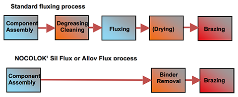
Fig. 3: Production steps for brazing line with standard wet fluxing and for NOCOLOK® Sil Flux
Furnace atmosphere: The brazing furnaces are delivered with various systems on nitrogen feeding nozzles. Therefore one of the most important questions is: ”What is the principle for setting the nitrogen flow through the brazing furnace?” This is shown in fig. 4.
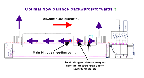
Fig. 4: Schematic of continues brazing furnace with recommended nitrogen flow balance
Joint geometry: By joint geometry one should understand the gap size between the elements to be joined and also the shape of the joint. The gap size for at least one component clad with filler alloy should be no larger than 0.15 mm and it should be remembered that along the joint there must be at least one point of intimate contact between the joint elements. The shape of the joints should be designed in such a way that there are no preferential paths for the filler alloy to flow. This concept called “competing joints” is explained in details in [6].
Filler alloy availability: This parameter is best expressed by the question: ”How much of the clad alloy actually forms the joint?” It is a common belief that there is as much filler metal available as clad material is rolled on the base metal. This, however, is never the case! During the heating cycle there is always some diffusion of silicon from the filler alloy into the matrix which diminishes the overall volume of liquid formed at brazing temperature. Sometimes even with a thick clad layer, only a fraction of the filler volume flows to form joints. Such an extreme limitation of the available liquid filler metal is connected with a phenomenon called “Liquid Film Migration [LFM]”. It is a phenomenon of very rapid diffusion of silicon into the matrix alloy. It starts at temperatures below the brazing window. This creates a moving liquid interface, which sweeps from the clad/ core interface into the core of the material. In this way the volume of available clad is diminished – thus making filling the larger gaps much more difficult. The degree of LFM correlates with cold work induced to the base metal before brazing through forming, bending and stamping and also strongly depends on the alloy type of the part [7].
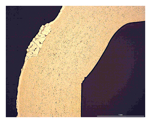
Fig. 5: Localized LFM on a manifold clad surface
Cleanliness: A question often raised about cleanliness is: ”How do we determine if a part is clean enough for successful brazing?” The fact is that cleanliness is a parameter for which there is no practical quantitative measure. Therefore, it is rather controlled by experience and the so called “good industrial practice”. Quite often an examination of the parts either before or after brazing is not sufficient to determine that the parts were not clean enough. Optical microscopy of the brazed joint or an investigation by Scanning Electron Microscope, in most cases determines if the root cause of the failure was connected with cleanliness. Sometimes insufficient degreasing or binder removal can be the reason for lack of braze (see fig. 6).
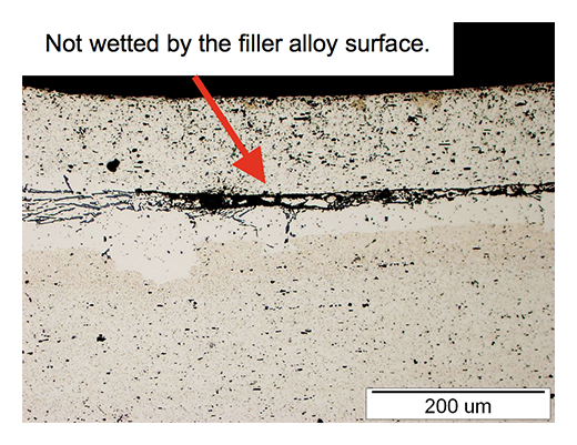
Fig. 6: Lack of braze due to insufficient cleanliness of one of the joint surfaces
References:
4. Hans W. Swidersky, “Aluminium Brazing with Non-Corrosive Fluxes – State of the Art and Trends in NO-COLOK® Flux Technology”, 6th International Confer-ence on Brazing, High Temperature Brazing and Dif-fusion Bonding (LÖT 2001), Aachen, Germany (May 2001)
5. Leszek Orman, Hans W. Swidersky, ”Interaction of NOCOLOK® Sil Flux with Aluminum Base Alloy at Various Conditions”, AFC- Holcroft 12th International Invitational Aluminum Brazing Seminar 2007
6. Ralph Woods “CAB Brazing Metallurgy”, AFC- Holcroft 12th International Invitational Aluminum Brazing Seminar 2007
7. Aad Wittebrood, “Microstructural Changes in Brazing Sheet due to Solid-Liquid Interaction” Corus Technology B. V., ISBN: 978-90-805661-6-3
Will be continued…