Concept and Definitions
In addition to the standard methods of applying flux to heat exchanger components (wet fluxing and dry fluxing), there is an increasing trend to using sophisticated flux formulations for selective pre-fluxing of components and/or localized fluxing of complicated geometries. The driving force behind this trend is multi-faceted: heat exchanger manufacturers are seeking to out-source flux application, to partially or completely eliminate certain process elements (fluxer, degreaser) and the movement away from seam-welded and extruded tubes to folded tube technology.
Before describing flux pastes and paints in more detail, a few definitions are noteworthy:
- Flux Paint: Mixture of various powders mixed with a binder which is applied to as substrate in a thin layer. The coating is then converted to a solid film during a subsequent drying (curing) operation thereby adhering to the substrate.
- Paste: Any mixture of various powders mixed with a carrier. Generally used for application where flux and/or alloy is required for a target location on a heat exchanger assembly or component. The viscosity is adapted to fit the application.
- Binder: Complex organic compounds that upon curing, reacts to provide adhesion of flux particles to the coated surface.
- Additives: Organic or inorganic substances used to modify the rheological properties of a fluid.
- Curing: Drying of the flux painted parts usually with hot air (150°C). Liquid carrier, i.e., water and/or organic solvent(s) evaporate and the binder reacts to provide adhesion.
- Adhesion: Qualitative or quantitative measure by which bonding strength of the flux particles to the coated surface is determined.
- De-binding: Process of binder removal from the painted surface either in air or in the furnace atmosphere by the treatment with high temperature.
- Viscosity: a measure of resistance to gradual deformation by shear stress, corresponding to the informal concept of thickness.
- Thermogravimetric Analysis (TGA): A technique in which the mass of a substance is monitored as a function of temperature or time as the sample specimen is subjected to a controlled temperature program in a controlled atmosphere.
Paint Flux Characteristics – Viscosity
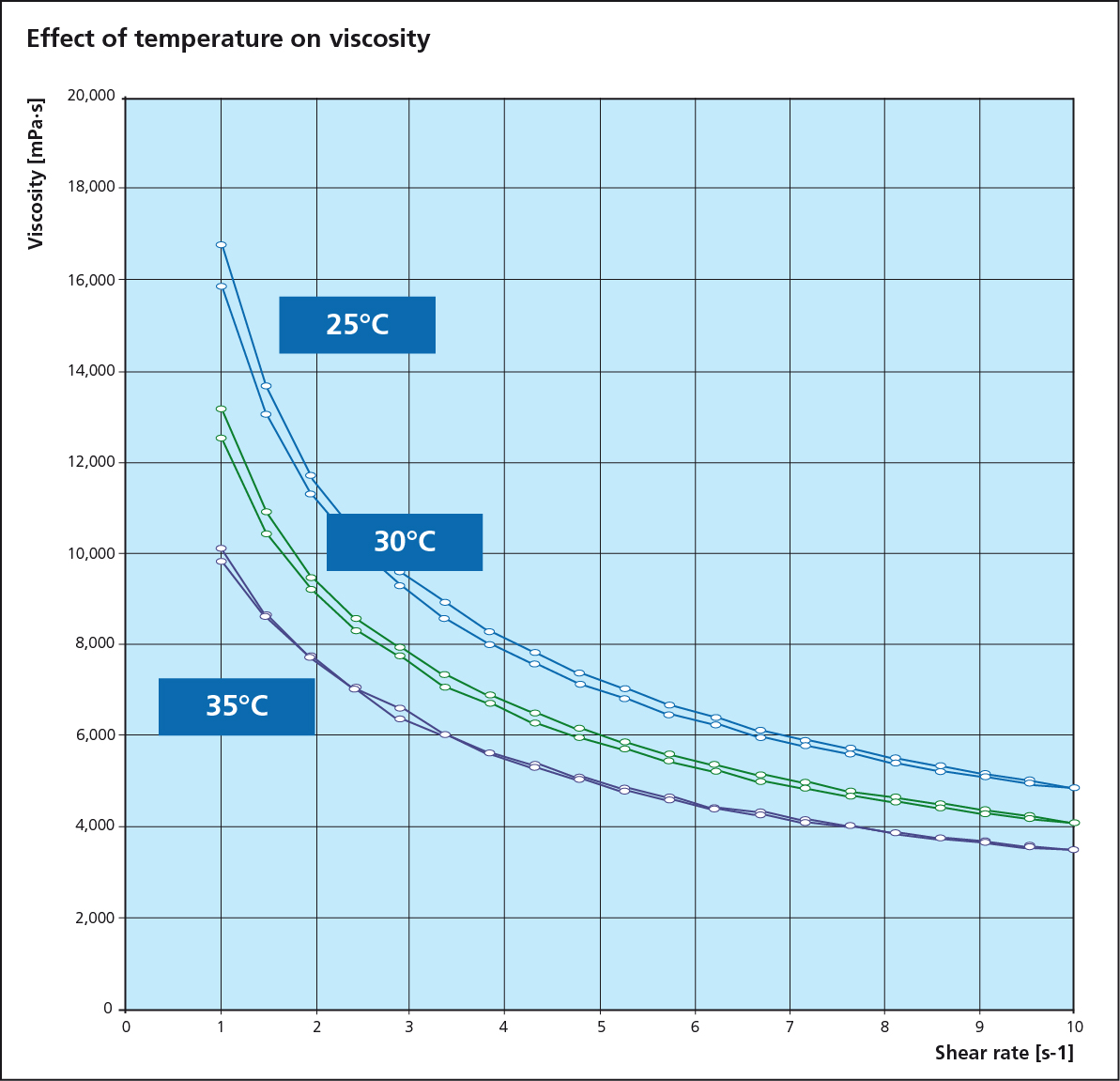
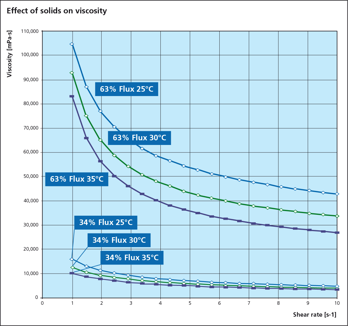
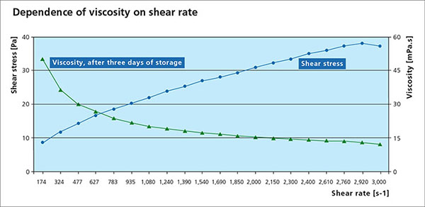
Viscosity is an essential parameter for the paint flux and is used to determine a suitable application process. A change in viscosity usually requires a change in the design of the application technique or equipment. All paste and paints used in fluxing are non-Newtonian fluids, meaning that the correlation between the applied shear stress and the shear rate is not linear. Many liquids, including paints are typical shear thinning fluids whose viscosities decreases non-linearly with shear stress. When providing a viscosity value, the methodology, specific shear rate and temperature must be provided.
Settling Behavior
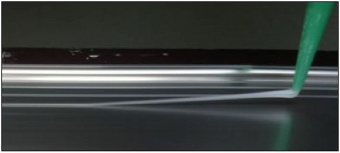
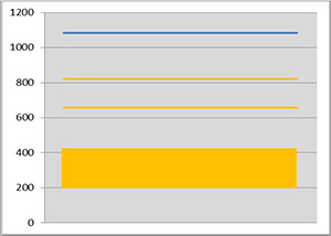
Flux powder has very low solubility in water and organic solvent based paint mixtures. During storage, the solid flux particles will eventually settle out, causing a separation of solids and liquid/carrier. The rate of settling and the ease for remixing is therefore an important practical characteristic. The photo below shows an example of different settling behaviors:
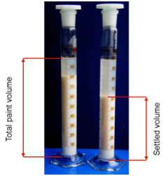
Note that the higher value of the settled volume at left means a slower process of settling.
The settling rate can be affected by several parameters such as binder concentration, flux solids content, storage time and temperature. To ensure complete homogeneity prior to use, a thorough remixing is necessary. Just shaking the container is usually not sufficient. It is recommended to use of a gyroscopic mixer which rotates the container around two perpendicular axes resulting in intensive material flow. These shear forces ensure optimal mixing without affecting the structure of the material.
Adhesion
The degree of paint flux adhesion varies depending on the heat exchanger manufacturer’s requirements. If paint fluxing is performed off-site and the material needs to be transported over long distances, a higher degree of adhesion is required than if the material is coated in house and simply needs to be transported from one station to the next. The degree of adhesion is typically controlled by the binder concentration in the formulation.
While there are standard methods for measuring adhesion (ASTM D 3359 Standard Methods for Measuring Adhesion by Tape Test), some paint flux users have developed their own in-house methods. The advantage of employing standard methods for measuring adhesion allows for a higher degree of inter-laboratory precision and comparison.
Binder Removal
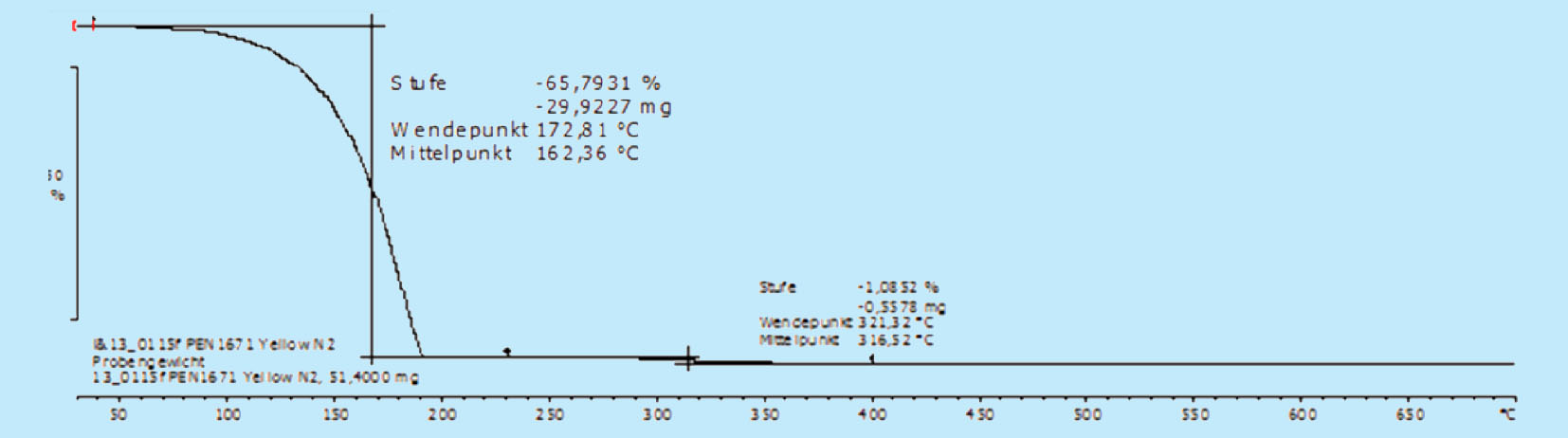
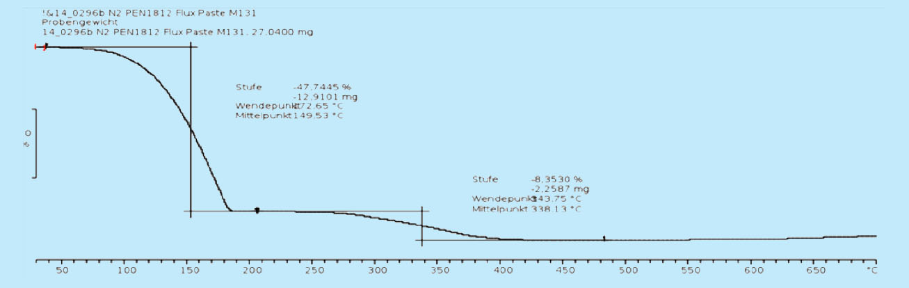
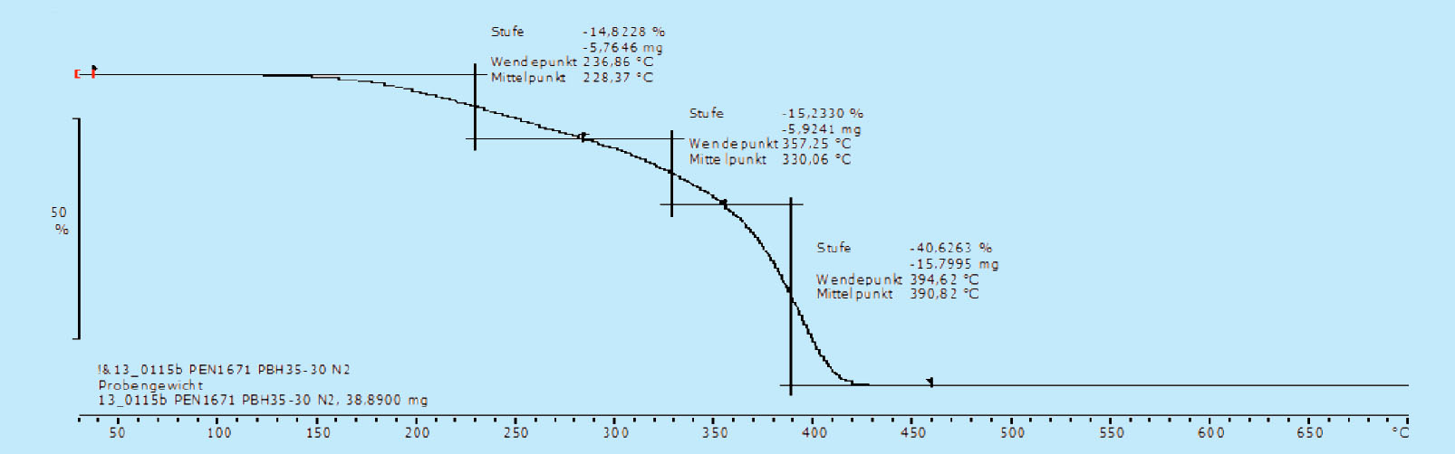
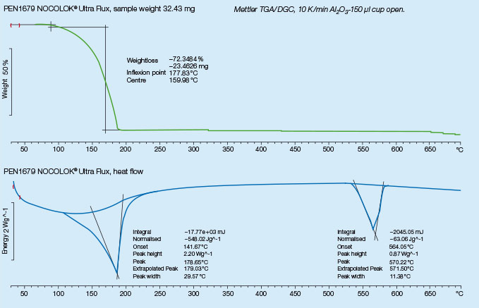
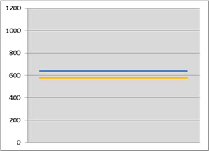
For successful brazing of paint fluxed aluminum components, the binder must be removed before reaching brazing temperature. In the production process, the paint flux carrier is removed immediately after coating in the dry-off / curing operation. When paint fluxed components are put into the brazing line, the increasing temperature is then responsible for decomposing and removing the binder by evaporation. The temperature range at which the binder is removed is determined by Thermogravimetric Analysis (TGA). With this technique, a simulated braze cycle is used to determine at which temperature the binder is removed. The TGA curves below shows the de-binding temperature for a typical paint flux formulation.
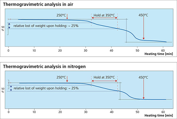
Note that whether in air or nitrogen, the binder removal temperature is in the range of 250°C to 450°C. This means that in this case, at least part of the binder will be removed in the brazing furnace. In continuous tunnel furnaces, this is not an issue since the binder evaporation products will be swept away by the counter flow of nitrogen. In semi-continuous or batch type furnaces, the potential influence of binder removal on equipment must be individually considered depending on each brazing line design. In most semi-continuous or batch type furnaces, binder removal takes place during the drying or preheating step in the presence of air – at temperatures below 400°C (to avoid formation of high-temperature oxides).
Special consideration must be given to paint fluxed components which are not boldly exposed to the furnace atmosphere. These areas are usually enclosed spaces such as inside manifolds, sandwiched evaporator plates and turbulators for charge air coolers. In these cases, de-binding products may remain trapped in the enclosed spaces and result in discoloration and black carbon residue deposits. In these cases, it may better to sacrifice some adhesion (lower binder concentration) in order to ensure adequate binder removal.
Paint Flux Machines
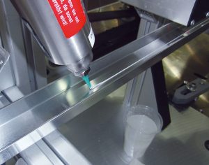
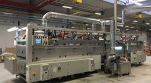 As the trend towards paint fluxing has increased, so has the sophistication of the paint flux machines. The industry has seen the evolution of paint fluxing from simple hand held paint sprayers, to semi-automatic machines incorporating a degreasing chamber, a paint flux spray chamber and drying/curing chamber. Today, the most sophisticated flux paint spray machines can be fully automated and fully integrated from the stamping operation through to core assembly. Machines with conveyor widths of 1500 mm, conveyor speeds of greater than 3.5 meters/minute which can spray top and bottom and be fully integrated with stamping and assembly are not uncommon. An example of such a machine is shown below:
To be continued…
Flux Paints and Pastes – Part 2


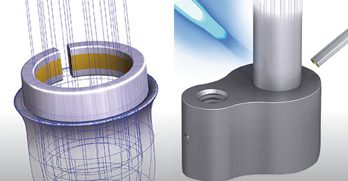
 Preciseness is essential for Al brazing.