Schlagwortarchiv für: CAB

Brazing aluminum products such as radiators, condensers, evaporators, etc. for the auto industry is a mass production process. The brazing operation is generally carried out in a mesh belt furnace under a nitrogen atmosphere and is commonly known as ‘CAB’ – Controlled Atmosphere Brazing.

entering furnace 1

Accurate temperature measurement of the product throughout the furnace can be critical. Using a ‘through furnace’ temperature profiling system to measure product temperature is common practice within the industry, and the benefits are well established. There are also some known disadvantages to using these types of systems and here we look at recent developments to overcome these problems.

profile 2

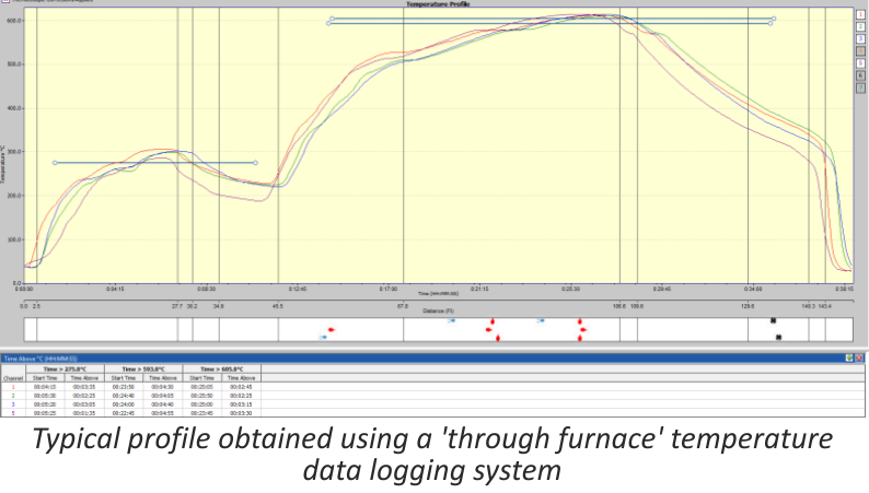
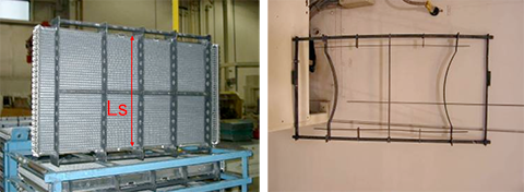
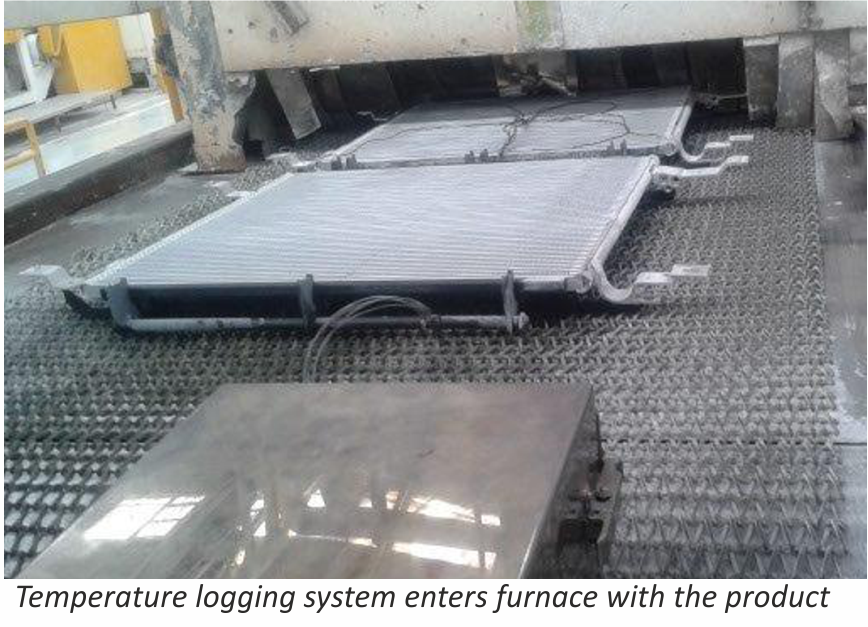
The ‘through furnace’ profiling system measures temperature by connecting thermocouples at specific points on the product which feed temperature information back to the data logger. The data logger is protected from the heat of the furnace by a ‘hot box’ or thermal barrier, allowing the system to travel through the furnace together with the product, storing valuable temperature data which is analysed at the end of the process using specialized software.

As previously stated the benefits of using temperature profiling systems are well known, however there are some disadvantages, these are:

  1. The thermal barrier normally has a very limited life span as parts of the insulation package are subject to acid attack from chemicals within the flux.
  2. Oxygen can leak from within the thermal barrier while it is in the furnace, potentially contaminating the nitrogen atmosphere.
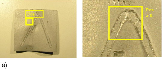
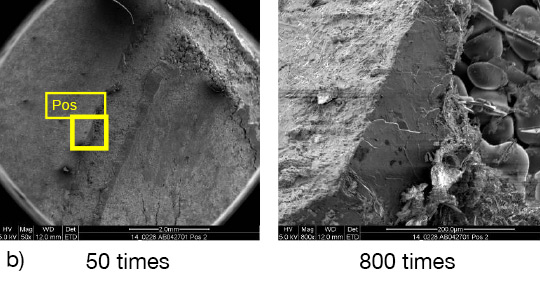
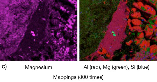
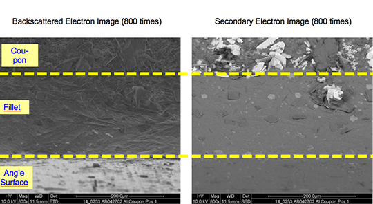
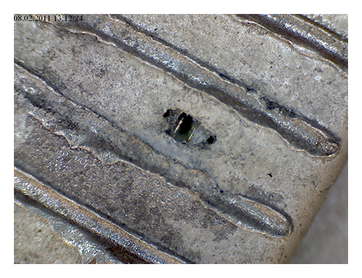
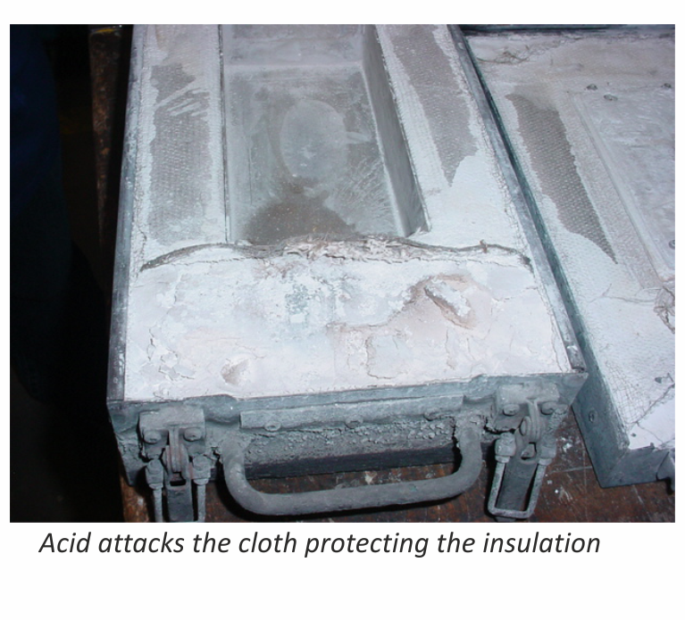
A. Acid attack

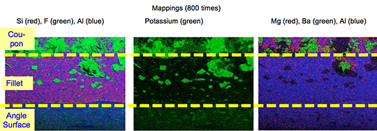
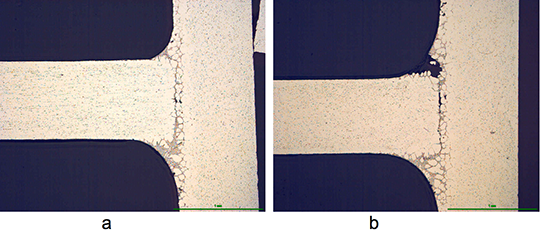
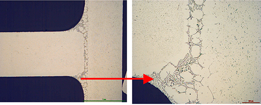
During the braze cycle, moisture in the air inside the ‘hot box’ or thermal barrier will combine with chemicals in the brazing flux to form hydrofluoric acid which attacks the high temperature cloth covering the microporous insulation. Once this cloth begins to break down, the unprotected insulation at the entrance to the ‘hot box’ wears away increasing the aperture where the thermocouples enter. This allows heat in, potentially damaging the data logger, and lets oxygen escape into the furnace atmosphere, which may affect braze quality.

damage

The life of this type of thermal barrier is severely reduced leading to high maintenance costs. The solution uses a robust ‘drawer’ design rather than the traditional ‘clam shell’ type.

combination5

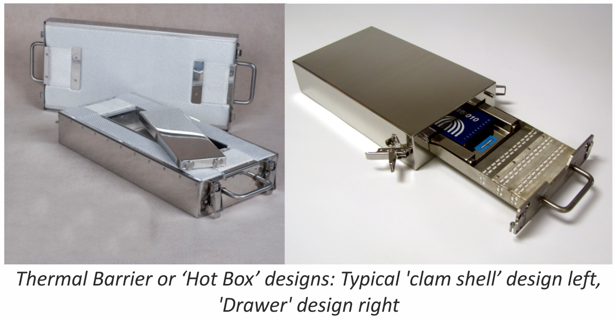
This eliminates exposure of the high temperature cloth to the aggressive flux atmosphere, and significantly increases the life of the barrier. This new type of thermal barrier has been used in daily production since April 2011 at many leading automotive parts suppliers, with one major North American auto manufacturer reporting over two thousand uses without any wear problems.

B. Oxygen leakage

Whether the thermal barrier is a ‘clam shell’ or ‘drawer’ type it will contain air. As the system travels through the furnace the air begins to warm up and expands. As it expands it begins to leak out into the furnace atmosphere, which may be an issue to some users.

air in barrier4

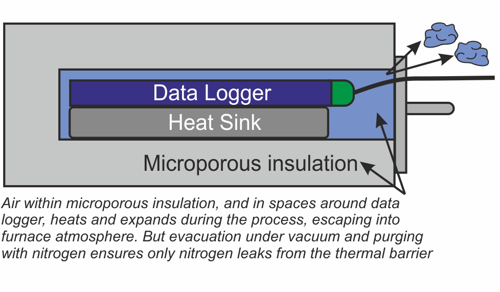
There are two areas within the thermal barrier where air will accumulate – within the microporous insulation, and in the spaces around the data logger and heat sink. A ‘two stage’ approach has been developed to remove this air.

Firstly eliminating the air deep within the microporous insulation is achieved by heating the whole thermal barrier or ‘hot box’ in a high vacuum, then back filling with nitrogen. This operation is carried out as the last stage in the manufacturing process.

Secondly, as an option for users with sensitive processes, all remaining air in the spaces around the data logger can be purged with low pressure nitrogen just prior to placing the system in the brazing furnace.

purge

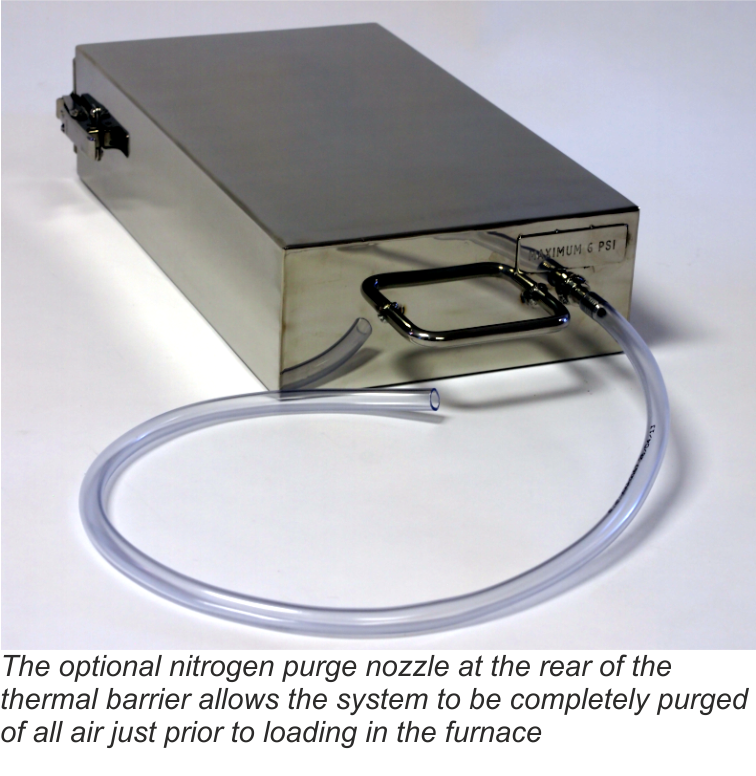
The nozzle for the nitrogen purge has been designed to allow free flow of the gas through the barrier, but by use of strategically placed internal ‘baffles’, heat penetration is minimized during the brazing process.

Conclusion

Although using a profiling system to monitor the product temperature in a CAB furnace has generally been considered high maintenance, it was judged that the value of the data obtained was worth the extra cost. However through careful system design a solution has been engineered that successfully overcomes these problems, saving maintenance costs and allowing the ‘hot box’ temperature profiling system to be used on a more regular basis.

Dave Plester, Director
Phoenix Temperature Measurement
www.phoenixtm.com
sales@phoenixtm.com

Approach to non-corrosive fluxes for further reduced residue solubility and improved magnesium tolerance
Technical Information by Ulrich Seseke-Koyro, Hans-Walter Swidersky, Leszek Orman, Andreas Becker, Alfred Ottmann
We split the article in four parts:

  1. Abstract and Basic Experimental Laboratory Procedures
  2. Reduced Flux Residue Solubility
  3. Improved Magnesium Tolerance
  4. Summary and Outlook

Summary

Our research activities so far have been focusing on flux blends with additives to validate lower water solubility of post braze flux residue. Another objective of this work was to allow for brazing of Al alloys with increased Mg levels using non corrosive fluxes.

First steps have been made with selected flux blends.  This paper reflects the current project status, but more work still needs to be done for further improvement.

Low flux residue solubility

It has been shown that the flux residue water solubility is reduced by combining KAlF4 with AEFs (“KAlF4 compound concept”); among them BaF2 being the most promising candidate.

Fluxes for higher Mg tolerance

Flux blends containing KAlF4 plus CsAlF4 and Li3AlF6 seem to be a promising approach to improve brazing of higher Mg containing aluminium alloys.

Aluminium coupons samples (AMAG 6951 with 0.68% Mg) for the base coupon and the angle (1.36% Mg in the joint interface) require flux loads as high as 15g/m2 for successful brazing.

Good joint formation can be achieved at 5g/m2 load on samples with 0.68% Mg content. Thus brazing of higher Mg level Al-alloys with appropriate flux mixtures at process-typical loads seems to be feasible.

Outlook

For the continuation of this project, we need to define the Mg range for real industrial aluminium heat exchanger needs. We think that this can best be done in a joint effort of HX manufacturer, Al material supplier and flux producer.


  1. P Garcia et al, Solubility Characteristics of Potassium Fluoroaluminate Flux and Residues, 2nd Int. Alum. Congress HVAC&R, Dusseldorf (2011)
  2. P Garcia et al., Solubility and Hydrolysis of Fluoroaluminates in Post-Braze Flux Residue, 13th AFC Holcroft Invitational Aluminum Brazing Seminar, Novi (2008)
  3. J Garcia et al, Brazeability of Aluminium Alloys Containing Magnesium by CAB Process Using Cs Flux, VTMS5, 2001-01-1763 (2001)
  4. H Johannson et al, Controlled Atmosphere Brazing of Heat Treatable Alloys With Cesium Flux, VTMS6 C599/03/2003 (2003)
  5. Handbook of Chemistry and Physics; Ref. BaSO4: 0.0025 g/l
  6. U Seseke, Structure and Effect – Mechanism of Flux Containing Cesium, 2nd Int. Alum. Brazing Con., Düsseldorf (2002)

Approach to non-corrosive fluxes for further reduced residue solubility and improved magnesium tolerance
Technical Information by Ulrich Seseke-Koyro, Hans-Walter Swidersky, Leszek Orman, Andreas Becker, Alfred Ottmann
We split the article in four parts:

  1. Abstract and Basic Experimental Laboratory Procedures
  2. Reduced Flux Residue Solubility
  3. Improved Magnesium Tolerance
  4. Summary and Outlook

Improved Magnesium tolerance

Mg additions to Al alloys contribute to higher strength properties. The ongoing trend in saving weight by down-gauging of Al sheet thickness requires sufficient mechanical stability. One option for the production of higher strength Al alloys is to increase the Mg content.

A disadvantage of Mg is the interaction with potas-sium fluoroamuminate fluxes during brazing, which results in poor joint formation [3] [4]. This effect, known as “flux poisoning”, is caused by the formation of high melting compounds. The addition of caesium and other metals to the flux helps to compensate to a certain degree the poisoning [6].

For the first set of laboratory brazing experiments we chose commercially available AMAG 6951 brazing sheet (0.68% Mg, 4343 clad) and clad-less AMAG angle material (0.68% Mg) to investigate the brazing performance and joint formation. In this situation the metal-to-metal interface adds up to 1.36% Mg (2 x 0.68%) in total.

Table 1 shows a list of representative flux combina-tions with NOCOLOK® types, KAlF4, Li3AlF6. CsAlF4, and AEFs.

We repeated all brazing tests with each sample three times.

Flux Type Load Fillet visual validation Comment
NOCOLOK® Cs Flux 10 g/m2 100% very small joint inconsistent seam
MD001212 LiCs24 10 g/m2 100% small joint weak seam
MD001223 LiCs43 10 g/m2 86% small joint inconsistent seam
AB039215 KAlF4/BaF2 10 g/m2 52% small joint inconsistent seam
NOCOLOK® Cs Flux 15 g/m2 100% weak seam
MD001212 LiCs24 15 g/m2 100% thicker than with NOC Cs Flux
MD001223 LiCs43 15 g/m2 100% thicker than with NOC Cs Flux
AB039215 KAlF4/BaF2 15 g/m2 98% weak seam slighly better than NOC Cs Flux

Table 1: Brazing trials: AMAG clad – AMAG clad-free angle different flux blends based on KAlF4 plus BaF2/Li3AlF6/CsAlF4

The angles from most of the AMAG specimens could be removed after brazing by pulling. Only a broken inner and outer fractured seam line was left – as can be seen below in picture 1 a.
flux_residus_part3_1
flux_residus_part3_2
flux_residus_part3_3

Picture 1: a) Photos, b) and c) SEM/EDX of NOCOLK® Cs Flux brazed sample (load 15 g/m²) Coupon 0.68% Mg, angle 0.68% Mg – angle removed by pulling

From the SEM analysis it is evident that a proper met-allurgical joint between base and angle has not been formed.

flux_residus_part3_4
flux_residus_part3_5

Picture 2: SEM/EDX analysis of aluminium ‘angle on coupon‘ brazed with KAlF4/BaF2 blend

There is flux residue present in the pulled apart fillet. This indicates that the liquid filler alloy was not capa-ble of pushing out completely the flux of the joint and it could be an explanation for the weakness of the fillet.

However, in case of the blend MD001212 LiCs24 with load 15g/m2 the joint structure is thorough as can be seen in picture 3 a).

flux_residus_part3_6

Picture 3: Microstructures of the brazed joints
a) Flux MD001212, load 15g/m2
b) Flux MD001223, load 15g/m2

It is worth mentioning when connecting blocks are brazed to condenser manifolds often a high load of manually applied flux is used in order to overcome the high Mg content in the block material. For such a case using the mixture MD001212 would allow for having quite high Mg content in the block material, which can be required by the designers of condens-ers.

The total concentration of 1.36% Mg (joint interface) is probably too high, because for most brazing applica-tions, a flux load of 15g/m2 is impractical. Thus, we decided to reduce the level of Mg in our samples to half – i.e. to 0.68% – by switching to an AA1050 (Al 99.5%) angle. We also reduced the flux load to a more process-typical level of 5g/m². The results are listed in table 2:

Flux Type Load Fillet visual validation Comment
MD001212 LiCs24 5 g/m2 100% good seam
NOCOLOK® Cs 5 g/m2 87% small joint

Table 2: Brazing tests AMAG coupon (0.68% Mg)/Al99.5 angle

The structure of the joint cross section below (picture 4) obtained with flux MD001212 LiCs24 shows good quality.

flux_residus_part3_7

Picture 4:Joint cross sections of alloys containing 0.68% Mg brazed with MD001212 LiCs24, load 5g/m2

To be continued…


  1. P Garcia et al, Solubility Characteristics of Potassium Fluoroaluminate Flux and Residues, 2nd Int. Alum. Congress HVAC&R, Dusseldorf (2011)
  2. P Garcia et al., Solubility and Hydrolysis of Fluoroaluminates in Post-Braze Flux Residue, 13th AFC Holcroft Invitational Aluminum Brazing Seminar, Novi (2008)
  3. J Garcia et al, Brazeability of Aluminium Alloys Containing Magnesium by CAB Process Using Cs Flux, VTMS5, 2001-01-1763 (2001)
  4. H Johannson et al, Controlled Atmosphere Brazing of Heat Treatable Alloys With Cesium Flux, VTMS6 C599/03/2003 (2003)
  5. Handbook of Chemistry and Physics; Ref. BaSO4: 0.0025 g/l
  6. U Seseke, Structure and Effect – Mechanism of Flux Containing Cesium, 2nd Int. Alum. Brazing Con., Düsseldorf (2002)

Approach to non-corrosive fluxes for further reduced residue solubility and improved magnesium tolerance
Technical Information by Ulrich Seseke-Koyro, Hans-Walter Swidersky, Leszek Orman, Andreas Becker, Alfred Ottmann
We split the article in four parts:

  1. Abstract and Basic Experimental Laboratory Procedures
  2. Reduced Flux Residue Solubility
  3. Improved Magnesium Tolerance
  4. Summary and Outlook

Reduced Flux Residue Solubility

The water solubility of standard NOCOLOK® Flux is 4.5 g/l, whereas for post-braze flux residue (pbr) it is 2.7 g/l. Post-braze residue of NOCOLOK® Li Flux shows a solubility of 2.2 g/l [1].

In the periodic table of chemical elements the group I fluorides have a reasonable low solubility (LiF: 2.7g/l [20°C]), but their Al-F-complexes much lower (Li3AlF6: 1.1g/l , K2LiAlF6: 0.3g/l with about 183 mg F-/l, K3AlF6: 2g/l), the group II fluorides (Alkaline Earth Fluorides “AEF”) show very low solubility (MgF2: 0.13g/l, CaF2: 0.016g/l, SrF2: 0.12g/l [25°C], BaF2: 0.12g/l [25°C]) [5]. Based on the facts of the dissolution behaviour of NOCOLOK® Li and the much lower solubility of the AEFs, we started investigating combinations of potas-sium fluoroaluminate fluxes with selected AEFs to combine the brazing characteristics of NOCOLOK® type flux with the very low solubility of AEF.

NOCOLOK® Flux consists of potassium fluoroalumi-nates with a specific ratio of KAlF4 and K2AlF5. Each of these compounds has different solubility. The combination of the (pure) compounds with different AEFs was of our main interest. We melted and pulverized the flux blends, dissolved them in a defined amount of DI-water and analyzed for K, Al and F.

The data achieved form these experiments is illus-trated in figure 1:

Flux-Residue-dia-1

Fig. 1: Solubility of flux blends – melted and pulverized
(lines are used to illustrate differences of the blends)

Considering minor statistical variations, the results look quite reasonable, with the blend of NOCOLOK® Li/BaF2 showing the lowest K value. This observation can be explained by the low solubility of NOCOLOK® Li Flux. Of more relevance is the actual post-braze solubility (flux residue) on brazed Al surfaces. Interactions of base material and molten filler metal may have a more complex chemical impact on the solubility behaviour

The results from coupon brazing under laboratory conditions and the solubility of the flux residue can be seen in figure 2.

Flux-Residue-dia-2

Fig. 2: Post-braze fluoride solubility of selected flux/ AEF combinations on Al coupons
(lines are used to illustrate differences of the blends)

Among the combination of NOCOLOK® type fluxes with diverse AEF additions, KAlF4/BaF2 shows the lowest residue F– solubility, i.e. 4mg/l. All our laboratory brazing tests with the samples showed the same good results like with standard NOCOLOK® Flux.

Corrosion comparison tests will be subject for future investigations.

To be continued…


  1. P Garcia et al, Solubility Characteristics of Potassium Fluoroaluminate Flux and Residues, 2nd Int. Alum. Congress HVAC&R, Dusseldorf (2011)
  2. P Garcia et al., Solubility and Hydrolysis of Fluoroaluminates in Post-Braze Flux Residue, 13th AFC Holcroft Invitational Aluminum Brazing Seminar, Novi (2008)
  3. J Garcia et al, Brazeability of Aluminium Alloys Containing Magnesium by CAB Process Using Cs Flux, VTMS5, 2001-01-1763 (2001)
  4. H Johannson et al, Controlled Atmosphere Brazing of Heat Treatable Alloys With Cesium Flux, VTMS6 C599/03/2003 (2003)
  5. Handbook of Chemistry and Physics; Ref. BaSO4: 0.0025 g/l
  6. U Seseke, Structure and Effect – Mechanism of Flux Containing Cesium, 2nd Int. Alum. Brazing Con., Düsseldorf (2002)

Approach to non-corrosive fluxes for further reduced residue solubility and improved magnesium tolerance

Technical Information by Ulrich Seseke-Koyro, Hans-Walter Swidersky, Leszek Orman, Andreas Becker, Alfred Ottmann

We split the article in four parts:

  1. Abstract and Basic Experimental Laboratory Procedures
  2. Reduced Flux Residue Solubility
  3. Improved Magnesium Tolerance
  4. Summary and Outlook

Abstract


For more than 30 years, potassium fluoroaluminates (NOCOLOK®) fluxes are already successfully used in controlled atmosphere brazing (CAB) of aluminium heat exchangers. Residues of these so-called non-corrosive fluxes have very low – but evident – solubility in water [1] [2]. In the discussion about corrosion of CAB produced aluminium heat exchangers, the flux residue solubility is an important parameter. There are concerns that – in addition to several other factors – fluoride ions (F–) potentially released from dissolved residue play a role in aluminium corrosion.

A theoretical option to address this point is the development of virtually insoluble flux. More realistic, however, will be fluxes with less soluble residues than the current compositions.

Some commercialised NOCOLOK® derivates, like NOCOLOK® Li Flux show already reduced solubility when compared to the standard product [1]. While investigating the chemical possibilities for further minimising the residue solubility and the release of F- ions, we have developed NOCOLOK® variants in combination with selected inorganic fluorides.

During this R&D project we also looked closely at the brazing properties of the new fluxes – with a focus on their performance for brazing of aluminium alloys with higher magnesium level. The current maximum magnesium range suitable for CAB with standard NOCOLOK® Flux is approximately 0.3%. Some improvement can be seen when using caesium-containing NOCOLOK® formulations (up to 0.5% Mg) [3] [4]. Some of the new fluxes we developed for further reduced residue solubility surprisingly show higher magnesium tolerance. This article summarizes the results of our laboratory work related to the development of fluxes with further reduced residue fluorides solubility and improved magnesium tolerance.

Basic experimental laboratory procedures


1. Lab brazing and alloy specimen setup
For experimental lab furnace brazing we used standard CAB brazing profile and 25 by 25 mm clad sheet coupons (single side) with angle on top. In case of the Mg topic an AMAG (Austria Metal AG) clad alloy (6951/4343) was brazed with an AMAG clad-less angle. Fluxing was done manually (flux load weight on precision scale, drops of isopropanol and homogenous spreading).

Test coupon

2. Solubility data generation
Coupon (3003/4343) with Al angle (Al 99.5%) were manually coated with a dedicated amount of flux blend and brazed as described in point 1. Brazed samples were placed in PET bottles and a defined quantity of demineralised water was added. Daily visual control and air exposure (by opening and closing the lid) was done.

PET-Flasche_klar

To be continued…


  1. P Garcia et al, Solubility Characteristics of Potassium Fluoroaluminate Flux and Residues, 2nd Int. Alum. Congress HVAC&R, Dusseldorf (2011)
  2. P Garcia et al., Solubility and Hydrolysis of Fluoroaluminates in Post-Braze Flux Residue, 13th AFC Holcroft Invitational Aluminum Brazing Seminar, Novi (2008)
  3. J Garcia et al, Brazeability of Aluminium Alloys Containing Magnesium by CAB Process Using Cs Flux, VTMS5, 2001-01-1763 (2001)
  4. H Johannson et al, Controlled Atmosphere Brazing of Heat Treatable Alloys With Cesium Flux, VTMS6 C599/03/2003 (2003)
  5. Handbook of Chemistry and Physics; Ref. BaSO4: 0.0025 g/l
  6. U Seseke, Structure and Effect – Mechanism of Flux Containing Cesium, 2nd Int. Alum. Brazing Con., Düsseldorf (2002)

Summary

The article was written on the basis of frequently asked questions from companies which either wanted to start a new all-aluminium brazing production of heat exchangers or wanted to convert from copper and aluminium mechanical assembly design to all-aluminium brazed parts. The questions were grouped into three main categories: Equipment (emphasis on assembling process), Process (emphasis on different fluxes and fluxing methods) and Corrosion.

Specific production challenges are also presented, which are important not only to newcomers of all-aluminium brazed heat exchangers, but to established companies as well. These include typical brazing problems such as managing leaks and the basics of brazing copper to aluminium. These topics are discussed by their relevance to the brazing parameters and their role in successful brazing.

Content:

  1. Introduction (Part 1, issue July 2013)
  2. Equipment (Part 1, issue July 2013)
  3. Brazing process (Part 2, issue August 2013)
  4. Brazing copper to aluminium (in this issue)
  5. Corrosion resistance (in this issue)
  6. Summary (in this issue)

4. Brazing copper to aluminium

When replacing a heat exchanger in an existing design, very often the connecting pipes are made from copper. Therefore the typical question: ”Is it possible to braze aluminium pipe to a copper one?” The answer is: Yes, it is possible by flame brazing. At 548°C there is the formation of a eutectic between copper and aluminium. This reaction is very rapid; therefore accurate temperature control and short process times such as with flame brazing are required. It is easier to braze at a temperature below the eutectic formation, thus lower melting point filler alloy and flux are required. In this case the recommended filler alloy would be ZnAl and Cs-Al-F flux. When copper remains in contact with aluminium for a longer period of time, such as in furnace brazing, an intensive dissolution of aluminium is observed. Therefore, for any factory which has production of copper and aluminium brazed exchangers, it is of very high importance to keep those two activities well separated from each other. A result of contamination of a condenser tube with a small chip of copper is shown in fig 7.

Fig. 7: Hole in a brazed tube surface burned through by a copper chip

Fig. 7: Hole in a brazed tube surface burned through by a copper chip

When joining copper to aluminium it must be remembered that extreme galvanic corrosion can take place when the joint is exposed to a humid or wet environment. It is therefore obligatory to make sure that Cu-Al joints are not exposed to water during service. This can be achieved for example by using temperature shrinking plastic sleeves over the tube joint.

5. Corrosion resistance

Corrosion resistance of condensers for air conditioning system is one of the major utility properties. Thus the first question: ”Is there any approved test for determining the corrosion resistance requirements for HVAC heat exchangers?” Unfortunately the HVAC industry has not yet developed a commonly accepted test standard for assessing corrosion resistance. In the automotive world, the most common tests used by manufacturers are:

  • SWAAT (ASTM G85 annex A3) – seawater acidified test, cyclic; it is an aggressive corrosion test commonly used in the automotive industry, but the characteristic of the test does not correspond well to the working conditions of stationary units.
  • Salt Spray Test (ASTM-B-117, ISO 9227), it is a test better reflecting the working conditions of stationary units, but it is not sufficiently aggressive (too long time for completion).

Other methods developed in response to observed corrosion due to rain or condensation water remaining on the units for a prolonged time, is the socalled soaking or water-exposure test. In this experiment a small cut-out heat exchanger section is immersed in demineralized water for a certain period of time and the concentration of ions in the water after soaking is analyzed. The procedure has not been standardized, therefore it is not really possible to compare results obtained by different companies, but the test can be used for direct comparison of different fluxes and materials. For now no correlation between its results and real life time has been established.

Invariably many companies when considering production of brazed aluminium heat exchange ask a question: ”What sort of alloys should be chosen for the best corrosion performance?” This topic is quite complex and there is no single “best answer”. In the authors’ opinion the best method is to discuss the subject with the aluminium suppliers who have a lot of knowledge and experience in choosing the optimal aluminium alloys. Every heat exchanger is an assembly of different components and when considering its corrosion resistance, the alloys of individual elements should be looked at as a unit in which mutual interactions between each component are taking place.

There are many different working environments which will significantly influence the corrosion behaviour of the parts. According to [8] the following major types can be distinguished:

Coastal/Marine:
This environment is characterized by an abundance of sodium chloride and sulphur compounds carried by spray, fog or winds.

Industrial:
This environment can be much diversified, where sulphur and nitrogen contaminants are most notable.. Many of the gases emitted during different combustion processes come back to the ground in form of acid rain. Also this environment produces a lot of different small particles in the form of dust which covers the equipment creating potential increased corrosion hazards.

Combination Marine/Industrial:
A combination of the above two factor create the harshest environment for any HVAC equipment.

Urban:
This environment is characterized by high level of automobile and house heating emissions. These are mainly SO2 and NOx compounds resulting also in acid rains.

Rural:
Usually these are unpolluted areas; however in some cases pollution may appear with higher a concentration of ammonia and nitrogen originating from animal excrement and fertilizer use.

The best solution would be to choose the alloys according to the different working environments; this however has hardly ever been possible.

As a mater of fact, [8] suggests that in particularly aggressive environment the coils should always have additional protection layer/coating.

6. Summary

Thanks to technical advantages of brazed heat exchangers over the mechanical ones and driven by high copper prices, it seems that a change into all aluminium heat exchangers in the HVAC&R industry is inevitable. Though the process of conversion from copper and /or mechanically assembled heat exchangers is in most cases a significant challenge, when properly planned it can be done smoothly without any unpredictable surprises. The major aspects which should be considered are equipment choices with a special emphasis on the assembly method, selection of proper alloys and the most optimal fluxing technology. The required data for the project and investment decisions can be obtained by direct contacts with equipment and consumables manufacturers.


References:

8. Selection Guide: Environmental Corrosion Protec-tion, Carrier Corporation, Syracuse, New York, July 2009

Summary

The article was written on the basis of frequently asked questions from companies which either wanted to start a new all-aluminium brazing production of heat exchangers or wanted to convert from copper and aluminium mechanical assembly design to all-aluminium brazed parts. The questions were grouped into three main categories: Equipment (emphasis on assembling process), Process (emphasis on different fluxes and fluxing methods) and Corrosion.

Specific production challenges are also presented, which are important not only to newcomers of all-aluminium brazed heat exchangers, but to established companies as well. These include typical brazing problems such as managing leaks and the basics of brazing copper to aluminium. These topics are discussed by their relevance to the brazing parameters and their role in successful brazing.

Content:

  1. Introduction (Part 1, issue July 2013)
  2. Equipment (Part 1, issue July 2013)
  3. Brazing process (in this issue)
  4. Brazing copper to aluminium (in September issue)
  5. Corrosion resistance (in September issue)
  6. Summary (in September issue)

3. Brazing Process

Brazing parameters

Success or failure of any controlled atmosphere brazing process is always connected with brazing parameters. These are:

Temperature: The brazed part should achieve a surface temperature between 590°C and 605°C and remain at that temperature range between 2 to 3.5 minutes. The temperature must be measured by thermocouples placed directly on the brazed parts. To obtain the above condition the furnace temperature controls must be set according to the size of the part. The usual maximum set value is in the range of 620°C. Note that the furnace set temperature will always be higher than the maximum temperature reached on the component.

Flux load and uniformity: The goal of fluxing is to achieve uniform flux coating with a load between 3 and 5 g/m2. For more difficult joints, for example tube to header joints, slightly higher flux loads are often used.

There are two major methods for fluxing: by spraying flux water suspension all over the assembled part and electrostatic fluxing where the dry powder is sprayed over the part in a process similar to powder painting. These methods are described in detail in [4]. Recently precoating with pure flux or mixtures which produce filler alloy as well, has become increasingly popular. Precoating with NOCOLOK® Sil Flux in particular is often used for air conditioning condensers and evaporators (MPE designs). Properties and challenges connected with this technology are described in [5]. The choice of fluxing method has big impact on the process machinery. The fact is that any of the above methods when properly conducted secure the required flux load and its uniformity. Therefore the decision about the fluxing choice should be based on a cost calculation. The calculation needs to take into account the following categories: media, maintenance, environment (cost of waste utilization), raw materials and consumables, labour and investment costs (depreciation). The result is always a function of local factors and conditions.

Fig. 3: Production steps for brazing line with standard wet fluxing and for NOCOLOK® Sil Flux

Fig. 3: Production steps for brazing line with standard wet fluxing and for NOCOLOK® Sil Flux

Furnace atmosphere: The brazing furnaces are delivered with various systems on nitrogen feeding nozzles. Therefore one of the most important questions is: ”What is the principle for setting the nitrogen flow through the brazing furnace?” This is shown in fig. 4.

Fig. 4: Schematic of continues brazing furnace with recommended nitrogen flow balance

Fig. 4: Schematic of continues brazing furnace with recommended nitrogen flow balance

Joint geometry: By joint geometry one should understand the gap size between the elements to be joined and also the shape of the joint. The gap size for at least one component clad with filler alloy should be no larger than 0.15 mm and it should be remembered that along the joint there must be at least one point of intimate contact between the joint elements. The shape of the joints should be designed in such a way that there are no preferential paths for the filler alloy to flow. This concept called “competing joints” is explained in details in [6].

Filler alloy availability: This parameter is best expressed by the question: ”How much of the clad alloy actually forms the joint?” It is a common belief that there is as much filler metal available as clad material is rolled on the base metal. This, however, is never the case! During the heating cycle there is always some diffusion of silicon from the filler alloy into the matrix which diminishes the overall volume of liquid formed at brazing temperature. Sometimes even with a thick clad layer, only a fraction of the filler volume flows to form joints. Such an extreme limitation of the available liquid filler metal is connected with a phenomenon called “Liquid Film Migration [LFM]”. It is a phenomenon of very rapid diffusion of silicon into the matrix alloy. It starts at temperatures below the brazing window. This creates a moving liquid interface, which sweeps from the clad/ core interface into the core of the material. In this way the volume of available clad is diminished – thus making filling the larger gaps much more difficult. The degree of LFM correlates with cold work induced to the base metal before brazing through forming, bending and stamping and also strongly depends on the alloy type of the part [7].

Fig. 5: Localized LFM on a manifold clad surface

Fig. 5: Localized LFM on a manifold clad surface

Cleanliness: A question often raised about cleanliness is: ”How do we determine if a part is clean enough for successful brazing?” The fact is that cleanliness is a parameter for which there is no practical quantitative measure. Therefore, it is rather controlled by experience and the so called “good industrial practice”. Quite often an examination of the parts either before or after brazing is not sufficient to determine that the parts were not clean enough. Optical microscopy of the brazed joint or an investigation by Scanning Electron Microscope, in most cases determines if the root cause of the failure was connected with cleanliness. Sometimes insufficient degreasing or binder removal can be the reason for lack of braze (see fig. 6).

Fig. 6: Lack of braze due to insufficient cleanliness of one of the joint surfaces

Fig. 6: Lack of braze due to insufficient cleanliness of one of the joint surfaces


References:

4. Hans W. Swidersky, “Aluminium Brazing with Non-Corrosive Fluxes – State of the Art and Trends in NO-COLOK® Flux Technology”, 6th International Confer-ence on Brazing, High Temperature Brazing and Dif-fusion Bonding (LÖT 2001), Aachen, Germany (May 2001)

5. Leszek Orman, Hans W. Swidersky, ”Interaction of NOCOLOK® Sil Flux with Aluminum Base Alloy at Various Conditions”, AFC- Holcroft 12th International Invitational Aluminum Brazing Seminar 2007

6. Ralph Woods “CAB Brazing Metallurgy”, AFC- Holcroft 12th International Invitational Aluminum Brazing Seminar 2007

7. Aad Wittebrood, “Microstructural Changes in Brazing Sheet due to Solid-Liquid Interaction” Corus Technology B. V., ISBN: 978-90-805661-6-3

Will be continued…

Summary

The article was written on the basis of frequently asked questions from companies which either wanted to start a new all-aluminium brazing production of heat exchangers or wanted to convert from copper and aluminium mechanical assembly design to all-aluminium brazed parts. The questions were grouped into three main categories: Equipment (emphasis on assembling process), Process (emphasis on different fluxes and fluxing methods) and Corrosion.

Specific production challenges are also presented, which are important not only to newcomers of all-aluminium brazed heat exchangers, but to established companies as well. These include typical brazing problems such as managing leaks and the basics of brazing copper to aluminium. These topics are discussed by their relevance to the brazing parameters and their role in successful brazing.

Content:

  1. Introduction (in this issue)
  2. Equipment (in this issue)
  3. Brazing process (in August issue)
  4. Brazing copper to aluminium (in September issue)
  5. Corrosion resistance (in September issue)
  6. Summary (in September issue)

1. Introduction

Brazing Furnace

Increasing environmental concern has identified the air conditioning and refrigeration industry as one of the contributors to the greenhouse effect and ozone depletion.

Accordingly to [1] 15% of all electricity consumption in the developed world is used by the air conditioning and refrigerator industry. Increasing the efficiency of these heat transfer systems has the positive impact of decreasing electricity consumption and therefore the overall emission of CO2. The advantages of all aluminium brazed condensers in an air conditioning system are well described in [2]. For example one such case study [3] allowed for saving about 2700 USD during 6 months. The above advantages are currently well recognized by both the air conditioning manufacturers and their end users. It is our observation that the majority of the companies in the HVAC industry which have started or are about to start production of aluminium brazed heat exchangers have only limited experience with aluminium brazing; therefore providing them with maximum possible technical assistance from the supplier side is of high importance.

This article was written on the basis of our contacts with such companies having an aim to offer some assistance to all newcomers and companies facing some troubles with their new type of production.

2. Equipment

In most cases, the first question from a company that wants to start a new aluminium brazing activity is: “What kind of furnace should I buy?”

It is a complex issue which mainly depends on size of the products, its diversity and overall planned production volume. The general principles for the choice of the brazing furnace are shown in Fig. 1. It should be pointed out that the furnace manufacturers will make a brazing furnace customized to particular requirements of a given client.

Fig. 1: Basic principles for brazing furnace choice

Fig. 1: Basic principles for brazing furnace choice

Assembling units

In many cases the companies which are starting production of all aluminium brazed heat exchangers have been producing copper brazed heat exchangers. Therefore the natural question is: ”Can I use the same equipment which is used for copper units?”

The straight forward answer is: No! Aluminium requires high precision for assembling (recommended gap size is 0.1 to 0.15mm), which is hardly ever achieved for brazing copper parts. Also one should remember that any copper contamination on aluminium can cause catastrophic brazing failures (holes).

The process of component assembly can be done on a simple manual stacker or on machines with varying degrees of automation through to fully automated units. The level of automation should be mainly determined by the planned production volume, but also other factors such as local labour costs should also be considered.

Basic requirements for a manual assembling unit:

  1. Cores must be assembled on a perfectly flat heavy steel plate
  2. After laying out the tubes and fins, the tubes must be pushed precisely into position determined by the slots in the headers.
  3. To secure the above requirement:
    1. movement of the pusher must be allowed only in one direction (no side or up movement),
    2. travel distance must be accurately controlled – e.g. by mechanical block on the pusher,
    3. it is useful to have a special distances between tubes to secure the right spacing for each header slot,
    4. the vertical alignment of the tubes must be secured either by steel plate or by hammering the tubes with a special pad.
  4. Threading the headers on the tubes should be done in one single action which does not allow for any side or vertical deflection of the headers.
  5. After threading the headers the fixtures should be assembled and the tube pusher released.

The process of the part assembly is invariably connected with fixtures; these are the steel elements which hold the parts together during brazing and then removed after brazing. The most frequently asked question is: ”What should be the design of the brazing frames/fixtures?”

Basically there are rigid and elastic designs which allow for some expansion when the core is heated. For larger cores elastic design is preferred. This type of fixture is reusable, also known as a permanent fixture and can go through the brazing cycle several hundred times. Apart from that we could use single usage fixtures, known as disposable fixtures and these include steel wire and steel bands. The multi-use fixtures must be made of stainless steel and in most cases the single use fixtures are usually made of ordinary low carbon steel.

Fig. 2: Example of rigid and elastic fixtures

Fig. 2: Example of rigid and elastic fixtures

When designing the length of the fixture (distance marked in red as Ls in fig. 2, one must remember thatthere is a difference in thermal expansion coefficient between aluminium and steel. To compensate for this, the following assumption is made: The length of the steel fixture at brazing temperature must be equal to the nominal width of the aluminium exchanger at brazing temperature. On this basis, an equation can be used describing the linear change of dimensions with temperature.

Ls(1 + αstΔt) = Lo(1 + αalΔt)

Where:
Ls – length of steel fixture,
αst – thermal expansion coefficient for the fixture material,
αal – thermal expansion coefficient for aluminium,
Δt – Increase of the part temperature during brazing,
Lo – Nominal width of the part.

As an example, for a part having width of 900 mm and nominal tube spacing of 8 mm, solving this equation and taking into account the fact that after assembly there must be some pressure exerted by the fixture on the part, the length of the fixture should be 907.5 mm and the fin height 8.08 mm. The longer steel fixture is compensated by the increased fin height. It also means that after assembly the part will have a slightly barrel-like shape (bowed out at the sides).

The question: ”What final checks are required for brazed parts?”is also connected to equipment purchases. All brazed parts must be checked for leak tightness. The most simple method is the so called “under water test”. In this case the part is pressurized with air and lowered into a water bath to look for bubbles. However some end users require more accurate and reliable methods. In the automotive industry it is common to check condensers for leaks with high pressure and extremely sensitive helium leak detection devices.

Each product should be accepted by the end user. In every case the scope of acceptance tests should be agreed to between the manufacturer and the end users. Typical tests include burst pressure, thermal cycling and of course standard ones for heat transfer efficiency and pressure drop. As a general rule it can be said that all aluminium parts should meet all the requirements applied to copper/brass parts.


References:

1. Hans W. Swidersky, “Brazed Aluminium Heat Ex-changers for the Refrigeration and Air Conditioning Industry”, APT Aluminium News, 1-2009

2. Bjørn Vestergaard, “Brazed Aluminium Heat Ex-changers – Ask for the inexpensive features”, Seminar “Aluminium Process-Technology for HVACR Industry” Vienna, March 21st-23rd, 2007

3. Case Study – Harris County Sheriff’s Building, “Carrier Turn to the Experts” 2006 Carrier Corporation 05/06 04-811-10206

Will be continued…

Considerations
Fixtures are used to hold the braze assembly in place during brazing. Surfaces with molten filler metal are very “greasy” and the fixtures need to hold the shape and tolerances during heat-up. Fixtures may also be used to support attachments such as inlet or outlet tubes.
When considering the type or configuration of fixtures to use, there are a number of considerations to take into account. For example, differential expansion between fixture and braze assembly increases part compression significantly during heat-up. One must be acutely aware of the differences in the coefficients of thermal expansion between stainless steel and aluminum. Aluminum expands much faster than stainless steel and this must be taken into consideration when designing a fixture. This is important to prevent distortion of the heat exchanger at final brazing temperature.
It is also important to note that molten filler metal dissolves steel and stainless steel. It is important to minimize contact with filler metal. It is also possible for aluminum to braze to fixtures. It is therefore important to either use a brazing stop-off for surfaces in contact with aluminum or to oxidize the fixtures when new or after cleaning. This can be done simply by running the fixtures through the brazing furnace.

Permanent Fixtures
The most common type of fixtures for heat exchanger manufacturing are permanent fixtures, ones that are used over and over again. These are usually made and should be made from stainless steel to prevent rust contamination in the slurry tank. The preferred material for fixtures is AISI 309 or 316, but most stainless steel alloys are perfectly acceptable.
Springs may be used in the fixture to apply a certain “holding” pressure to the heat exchanger during brazing. However, the technique of using springs seems to be less common than in the past. More often now, fixtures are designed with fixed dimensions. The heat exchanger is compressed slightly and loaded into the fixture. When the source of compression is removed, the natural spring-back holds the heat exchanger in place against the fixture.

Cleaning
As flux builds up on permanent fixtures and may contaminate the flux slurry, it is necessary to routinely clean the fixtures to remove flux and other contaminants that may have accumulated. There is no convenient chemical cleaning method to remove flux residues. The most appropriate methods are by mechanical means such as wire brushing or grit-blasting.
Once the residues have been removed by one of the above methods, the fixtures should be oxidized by running them through the brazing furnace. Non-oxidized fixtures are likely to stick or even braze to the work piece.

Steel banding
An alternative to permanent fixtures is the use of disposable steel banding. Since mild steel can be used, material costs are kept to a minimum. Wax coated mild steel bands are often used to prevent the banding material from rusting that can contaminate the flux slurry and discolor the heat exchanger. The steel bands are used only once and are disposed of after brazing.
Steel banding requires experimentation to determine the appropriate tension and positioning. Thereafter, an automatic banding machine should be used to ensure consistency.

Article from the Newsletter of our sponsor Solvay Fluor:
New glass brazing furnace in the NOCOLOK Technical Center

Many visitors to seminars, trade shows or videos are already familiar with the test glass brazing furnace in the NOCOLOK Technical Center. The unique furnace now has a big brother. All components of the new test furnace, except for the radiant heater, were developed in own production at Solvay.

The fluorine research workshop in Hannover has done an excellent job, “The construction of such a furnace is only possible with the tremendous expertise of the colleagues in the test workshop,” says Andreas Becker, a Solvay Fluor research employee. “With the new glass furnace, it is possible to braze larger objects, such as aluminium wafers for refrigerant test series for automobile producers.”

Specially developed software can capture every stage of the brazing process as high-resolution images – so that not even the tiniest detail of the brazing process can escape the testers. The new furnace saves energy and time – test brazing series with larger objects no longer require the much larger Camlaw brazing furnace at the Technical Center.

The next stage of development is already being planned: in a unique process Solvay’s glass blowers have succeeded in forming a square glass body, which offers even more space for larger items.

An overview of all services from the NOCOLOK Technical Center is offered in the new brochure, which is available for download.