
A Combination of NOCOLOK® Zn Flux and NOCOLOK® Li Flux for Improved Corrosion Resistance Part 1
written by Leszek Orman, Radziszow / Poland; Hans-Walter Swidersky, Hannover / Germany
Abstract
In 2001 and in 2009 respectively, Solvay introduced two new fluxes for aluminium brazing: – NOCOLOK®Zn Flux (a ‘reactive flux’ – for the creation of precisely controlled sacrificial layers on part surfaces); and – NOCOLOK®Li Flux (for improving corrosion resistance of stationary air conditioning systems under stagnant water conditions).
When brazing with NOCOLOK®Li Flux, as validated on laboratory scale, some aluminium alloys show slightly better corrosion performance in SWAAT than parts brazed with standard flux.
On this basis, it was decided to investigate if a combination of NOCOLOK®Zn Flux and NOCOLOK®Li Flux can provide additional improvements in corrosion resistance.
Tubes of sample heat exchangers were coated with mixtures of Zn Flux and Li Flux – and brazed in an industrial furnace. Their corrosion resistance was checked by so-called soaking tests – i.e. by immersion in demineralized water over extended period of time.
In order to check the influence of NOCOLOK®Li Flux on corrosion resistance, some condensers were brazed under real industrial conditions, and their corrosion behavior was examined in SWAAT.
The results of this work indicate that a combination of NOCOLOK®Zn Flux and NOCOLOK®Li Flux can contribute to improved corrosion resistance at stagnant water conditions, and that NOCOLOK®Li Flux can delay corrosion attack in SWAAT.
1 Introduction
Corrosion resistance of heat exchangers exposed to different elements during service has been always one of the main concerns for the heat exchanger manufacturers and users. The most important methods for improving corrosion resistance of a given aluminium heat exchanger are: selecting alloys for the exchanger parts in such a way that the galvanic potentials of the exchanger elements are properly balanced; creation of a sacrificial layer on a given part of the exchangers (usually tube surfaces); and coating the whole exchanger with a protective layer, which prevents a direct contact of the environment elements with the metal of the heat exchanger.
A common method for the creation of a sacrificial layer on the tube surface involves introducing Zn into the outer layer of the tube material. Traditionally it is done by electro arc spraying of the extruded tubes with metallic Zn. To improve the uniformity of the Zn enriched layer and to enable better control of the Zn diffusion profile, NOCOLOK®Zn Flux was developed [1].
With the flux on the aluminium parts to be brazed, a thin strongly adhering layer of post brazed flux residue remains on the surfaces after brazing. Provided that this layer is uniform and covers all elements of the exchanger, it slightly improves corrosion resistance – acting as a barrier for element penetration [2]; however, for standard NOCOLOK®Flux this positive effect is not very strong.
Upon the introduction of all aluminium CAB produced condensers into stationary air conditioning systems, it was observed that the surfaces of such units – when exposed to stagnant water (for example from rain or condensation), can show signs of corrosion. In response to that situation NOCOLOK® Li Flux was developed. Reduced water solubility of NOCOLOK® Li Flux post braze flux residue has been attributed for slowing down corrosion rate of the brazed aluminium parts under stagnant water condition [3, 4]. Also it was observed that parts brazed with NOCOLOK® Li Flux (laboratory samples) show higher resistance to corrosion in SWAAT [5]. On this basis, it was decided to investigate whether a combination of NOCOLOK®Zn Flux and NOCOLOK®Li Flux can achieve further improvements of corrosion resistance, and if NOCOLOK®Li Flux can provide additional corrosion resistance for industrial parts in SWAAT.
2 Experimental
Determination of the flux mixture composition
In the first step of the experiment, brazing at industrial conditions of especially prepared mock-ups was performed (Fig.1). The primary task was to determine the correct proportion between the NOCOLOK® Zn Flux and Li cryolite (Li3AlF6). The mixture composition was established on an assumption that the lithium cryolite should react with K3AlF6(equation 2) in order to minimize the water solubility of the Post Braze Flux Residue [PBFR]. Thus the calculation was based on following reactions [1, 4]:
12 KZnF3 + 8 Al → 12 Zn + 6 KAlF4 + 2 K3AlF6 (1)
Li3AlF6 + 2 K3AlF6 → 3 K2LiAlF6 (2)
By adding the sides of equations 1 and 2 we obtain:
12 KZnF3 + 8 Al + Li3AlF6 → 12 Zn + 6 KAlF4 + 3 K2LiAlF6 (3)
Substituting the atomic masses into equation 3, we obtain that the composition of the flux mixture should be:
NOCOLOK®Zn Flux – 91.7%; lithium cryolite – 8.3% by weight. As stated in [6], a load in the range of 10 g/m2of Zn Flux (which corresponds to metallic level of Zn equal to 4g/m2) is sufficient for providing sacrificial layer on the substrate surface. In order to envelope the above value for the current experiment 3g/m2and 6g/m2of metallic Zn load were chosen. That corresponds to 8g/m2and 16g/m2of the NOCOLOK® Zn Flux + Lithium cryolite mixture. Further on this mixture is called NOCOLOK®ZnLi Flux.
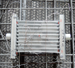
Fig. 1: The assembled mock up with Data Pack thermocouples just before brazing
Materials used in experiment:
- Flux: NOCOLOK® Zn Flux – 91.7% weight, lithium cryolite – 8.3% weight
- Fins: HA 3968-K
- Headers: HA 3905-R
- Tubes, alloy 1: HA 9108
- Tubes, alloy 2: HA 9170, both alloys coated on industrial machine (SAPA Precision Tubing) with NOCOLOK®ZnLi, load (8 and 16g/m2)
The fins, tubes and headers were manufactured by Hydro Aluminium Rolled Products.
Brazing of the mock ups was performed in industrial Active Only brazing line made by Seco/Warwick. As measured by Data Pack®, the parts stayed at temperature over 580°C for about 5 minutes.
After brazing the Zn diffusion profile and resistance to the so called soaking test were evaluated.
3 Results and discussion
Mock up experiment
Zn diffusion profiles was measured by X-ray microprobe JXA 8230 made by JEOL. Applied accelerating voltage: 15kV with the beam current 30nA. They were measured in two characteristic places: through the fin to tube joint and through the tube in the middle of the fin joints. This is shown in Fig. 2:


Fig. 2: Electron Back Scattered Image – example showing location of the analyses lines
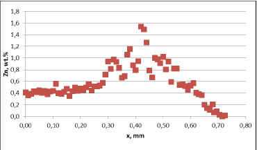
Fig. 3a: Zn diffusion profiles – as measured on the brazed mock ups, Diffusion profile across the joint, Flux load 8g/m2, tube alloy HA9180
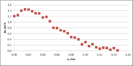
Fig. 3a: Zn diffusion profiles – as measured on the brazed mock ups, Diffusion profile between the joints, Flux load 8g/m2, tube alloy HA9180
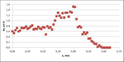
Fig. 3a: Zn diffusion profiles – as measured on the brazed mock ups, Diffusion profile across the joints, Flux load 16g/m2, tube alloy HA9170
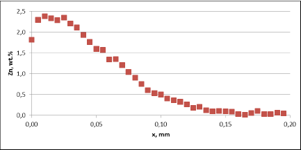
Fig. 3a: Zn diffusion profiles – as measured on the brazed mock ups, Diffusion profile between the joints, Flux load 16g/m2, tube alloy HA9170
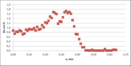
Fig. 3b: Zn diffusion profiles – as measured on the commercial sample, Spot 1, Diffusion profile across the joint
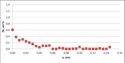
Fig. 3b: Zn diffusion profiles – as measured on the commercial sample, Spot 1, Diffusion profile between the joint
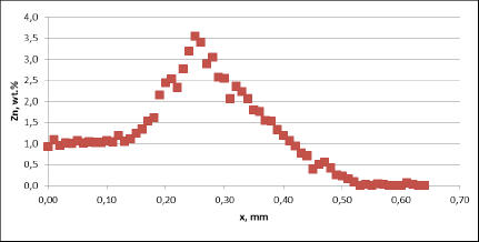
Fig. 3b: Zn diffusion profiles – as measured on the commercial sample, Spot 2, Diffusion profile across the joint
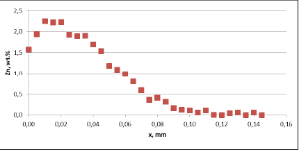
Fig. 3b: Zn diffusion profiles – as measured on the commercial sample, Spot 2, Diffusion profile between the joint
For all mock up samples the depth of diffusion profiles is around 120 microns. The maximum level of Zn concentration for lower flux load is at the range of 1.2% to 1.4% – and for higher flux load is in the range of 2.5%. These values seem to be typical for tubes coated with NOCOLOK®Zn Flux. Also the maximum content of Zn in the fillet seems to be rather well balanced with the Zn concentration on the tube surface (Fig. 3a).
For comparison, the diffusion profile of a commercial part was also investigated. In this case the diffusion profiles show quite significant differences – both in the depth of diffusion and the maximum Zn concentration on the tube surface. Also the Zn concentration is higher for fin to tube joint (Fig. 3b). This observation seems to be consistent with a well known fact that electric arc Zn coating is not uniform having places with high and low zinc load.
Literature
[1] A. Gray, H.W. Swidersky, L. Orman.
Reactive Zn Flux – an opportunity for controlled Zn diffusion and improved corrosion resistance. AFC Holcroft 11thInternational Invitational Brazing Seminar, October 2006
[2] A. Gray, A. Afseth, H.W. Swidersky. The influence of residual flux level on the corrosion behavior of heat exchanger materials, ASST, May 2003
[3] Solvay Patent. WO10060869 A1 – Anti-Corrosive Flux – NOCOLOK®Li Flux, 2010
[4] Solvay Patent. WO11098120 A1 – Flux Forming an Insoluble Brazing Residue – Li Flux – Li3AlF6, 2011
[5] NOCOLOK®Li Flux New Brazing Flux with Improved Residue Performance
Hinterlasse einen Kommentar
An der Diskussion beteiligen?Hinterlasse uns deinen Kommentar!