
Schlagwortarchiv für: Exchanger
During recent years, gel blockage in engine coolant systems with aluminum heat exchangers produced by CAB has gotten more and more attention in the automotive industry. A general understanding of gel formation processes in engine coolants and the role that flux residues on internal surfaces of brazed heat exchangers may or may not have is of significant interest.
written by Leszek Orman, Radziszow / Poland; Hans-Walter Swidersky, Hannover / Germany
3 Results and discussion / Part 2
Corrosion resistance of the mock up samples was checked in the so called soaking test. Exemplary structures are shown in fig. 4:
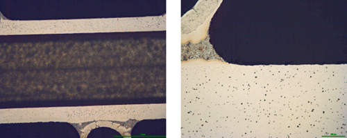
Fig. 4: Exemplary metallographic cross sections after 60 days of soaking (flux load 16g/m2, tube: HA 9170)
Observation of metallographic structures did not allow for a univocal statement that there are certain differences between investigated parts. In none of the investigated cases a fin debonding process was observed. At longer time of soaking, intensive corrosion of fins could be observed. More details were obtained when measuring the thickness of the tube walls. These results are presented in fig. 5:
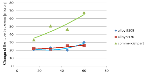
Fig. 5a: Change in the tube wall thickness as a function of soaking time – Time of soaking [days] – Flux load 8 g/m2

Fig. 5b: Change in the tube wall thickness as a function of soaking time – Time of soaking [days] – Flux load 16 g/m2
It seems that thinning of tubes at the beginning of the soaking test is quite rapid as compared to the period of soaking longer than 15 days. In case of the NOCOLOK® ZnLi Flux, the maximum tube thinning is in the range of 30 microns. The same maximum value for the commercial part is in the range of 65 microns. There is no significant difference in the tube thinning between the two tested different alloys.
Industrial test
The industrial test was performed with condensers used for stationary application. However, they had a typical design as for automotive. In this case – since the standard production tube were not zinc coated – the testing was done using NOCOLOK® Li Flux.
Material of the tested part:
Fins: FA 6815 clad 4343 both sides
Tubes: HA9108
Manifolds: HA3905-R outside clad HA4045-D
Brazing was performed on industrial brazing line made of wet fluxer, dryer and Active Only (Seco/Warwick) brazing furnace. Fluxing was done with NOCOLOK® Li Flux – concentration 13% for overhead spray and 43% for tube to manifolds joints. The above concentrations were the same as for standard industrial production. Also no changes were done in brazing parameters as compared to standard conditions.
Corrosion resistance of the brazed parts was checked by SWAAT (ASTM G85 A3). In order to examine the parts after different times at SWAAT, a brazed part was segmented, and all the segments were tested in the same test chamber – but for different time periods.
Examination of the segments after 5 days in SWAAT did not reveal any significant progress of corrosion; however, after longer times, fin debonding was observed. This examination did not show any differences between the parts fluxed with NOCOLOK® Li Flux and those fluxed with standard NOCOLOK® Flux. More information was obtained when examining metallographic cross sections:
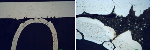
Fig. 6a: Structure of the samples brazed with NOCOLOK® Flux after 5 days in SWAAT
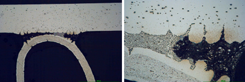
Fig. 6b: Structure of the samples brazed with NOCOLOK® Li Flux after 5 days in SWAAT
It can be observe that initially corrosion starts as intergranular attack on the fin material and as an intensive attack on the filler alloy. The filler is attacked selectively; firstly the alpha phase of the eutectic is removed.
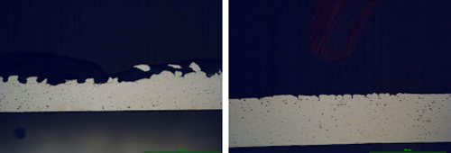
Fig. 7: Structure of samples brazed with NOCOLOK® Flux (left) and NOCOLOK® Li Flux (right) flux after 60 days in SWAAT
Already after 30 days of SWAAT, for both sample almost all the fins were detached from the tubes – thus the examination of the parts after 60 days of SWAAT was limited only to the tubes.
The surface of the tube in case of standard NOCOLOK® is corroded to a much higher degree than in the case of the part brazed with NOCOLOK® Li Flux. The corrosion in both cases is initiated by intergranular attack; however later on it does not develop into pitting corrosion, but the removal of the tube material has laminar character. It seems that NOCOLOK® Li Flux did not cause a change of the corrosion mechanism; it just delayed the corrosion processes.
The higher corrosion rate for samples brazed with standard NOCOLOK® Flux observed in the microscopic structures has been confirmed by measuring the tube wall thickness. Results of those measurements (at least 10 measurements per point) are presented in fig. 8. It should be worth noticing that the standard variation for the wall thickness measured after 60 days of SWAAT was 10.9µm for fluxing with NOCOLOK® Li Flux and 81.2µm for fluxing with standard NOCOLOK® Flux. Such a large variation in the wall thickness in case of NOCOLOK® Flux would indicate that the “long life” capacity of the protection mechanism in this case was practically exhausted.
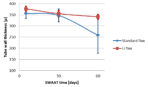
Fig. 8: Thinning of the tube wall during SWAAT
4 Conclusions
The experiment with the mock ups allowed for conclusions that there is no negative influence of NOCOLOK® Li Flux on the creation of Zn enriched sacrificial layer. Presence of NOCOLOK® Li Flux in the mixture allowed for better protection of the sample parts against corrosion in stagnant water test. One objective of stagnant water corrosion test is the simulation of stationary air conditioning unit humidity exposure.
It is possible to utilize in a flux mixture advantages of NOCOLOK® Zn and of NOCOLOK® Li. Also as shown by testing with two different tube alloys, there is no significant difference in the tube thinning between different alloys.
Initial laboratory observations – that NOCOLOK® Li Flux improves resistance to corrosion in SWAAT condition – have been proven on industrial part. Thus one option to increase the life time during SWAAT can be to use NOCOLOK® Li Flux.
Literature
[1] A. Gray, H.W. Swidersky, L. Orman.
Reactive Zn Flux – an opportunity for controlled Zn diffusion and improved corrosion resistance. AFC Holcroft 11thInternational Invitational Brazing Seminar, October 2006
[2] A. Gray, A. Afseth, H.W. Swidersky. The influence of residual flux level on the corrosion behavior of heat exchanger materials, ASST, May 2003
[3] Solvay Patent. WO10060869 A1 – Anti-Corrosive Flux – NOCOLOK®Li Flux, 2010
[4] Solvay Patent. WO11098120 A1 – Flux Forming an Insoluble Brazing Residue – Li Flux – Li3AlF6, 2011
[5] NOCOLOK®Li Flux New Brazing Flux with Improved Residue Performance
written by Leszek Orman, Radziszow / Poland; Hans-Walter Swidersky, Hannover / Germany
Abstract
In 2001 and in 2009 respectively, Solvay introduced two new fluxes for aluminium brazing: – NOCOLOK®Zn Flux (a ‘reactive flux’ – for the creation of precisely controlled sacrificial layers on part surfaces); and – NOCOLOK®Li Flux (for improving corrosion resistance of stationary air conditioning systems under stagnant water conditions).
When brazing with NOCOLOK®Li Flux, as validated on laboratory scale, some aluminium alloys show slightly better corrosion performance in SWAAT than parts brazed with standard flux.
On this basis, it was decided to investigate if a combination of NOCOLOK®Zn Flux and NOCOLOK®Li Flux can provide additional improvements in corrosion resistance.
Tubes of sample heat exchangers were coated with mixtures of Zn Flux and Li Flux – and brazed in an industrial furnace. Their corrosion resistance was checked by so-called soaking tests – i.e. by immersion in demineralized water over extended period of time.
In order to check the influence of NOCOLOK®Li Flux on corrosion resistance, some condensers were brazed under real industrial conditions, and their corrosion behavior was examined in SWAAT.
The results of this work indicate that a combination of NOCOLOK®Zn Flux and NOCOLOK®Li Flux can contribute to improved corrosion resistance at stagnant water conditions, and that NOCOLOK®Li Flux can delay corrosion attack in SWAAT.
1 Introduction
Corrosion resistance of heat exchangers exposed to different elements during service has been always one of the main concerns for the heat exchanger manufacturers and users. The most important methods for improving corrosion resistance of a given aluminium heat exchanger are: selecting alloys for the exchanger parts in such a way that the galvanic potentials of the exchanger elements are properly balanced; creation of a sacrificial layer on a given part of the exchangers (usually tube surfaces); and coating the whole exchanger with a protective layer, which prevents a direct contact of the environment elements with the metal of the heat exchanger.
A common method for the creation of a sacrificial layer on the tube surface involves introducing Zn into the outer layer of the tube material. Traditionally it is done by electro arc spraying of the extruded tubes with metallic Zn. To improve the uniformity of the Zn enriched layer and to enable better control of the Zn diffusion profile, NOCOLOK®Zn Flux was developed [1].
With the flux on the aluminium parts to be brazed, a thin strongly adhering layer of post brazed flux residue remains on the surfaces after brazing. Provided that this layer is uniform and covers all elements of the exchanger, it slightly improves corrosion resistance – acting as a barrier for element penetration [2]; however, for standard NOCOLOK®Flux this positive effect is not very strong.
Upon the introduction of all aluminium CAB produced condensers into stationary air conditioning systems, it was observed that the surfaces of such units – when exposed to stagnant water (for example from rain or condensation), can show signs of corrosion. In response to that situation NOCOLOK® Li Flux was developed. Reduced water solubility of NOCOLOK® Li Flux post braze flux residue has been attributed for slowing down corrosion rate of the brazed aluminium parts under stagnant water condition [3, 4]. Also it was observed that parts brazed with NOCOLOK® Li Flux (laboratory samples) show higher resistance to corrosion in SWAAT [5]. On this basis, it was decided to investigate whether a combination of NOCOLOK®Zn Flux and NOCOLOK®Li Flux can achieve further improvements of corrosion resistance, and if NOCOLOK®Li Flux can provide additional corrosion resistance for industrial parts in SWAAT.
2 Experimental
Determination of the flux mixture composition
In the first step of the experiment, brazing at industrial conditions of especially prepared mock-ups was performed (Fig.1). The primary task was to determine the correct proportion between the NOCOLOK® Zn Flux and Li cryolite (Li3AlF6). The mixture composition was established on an assumption that the lithium cryolite should react with K3AlF6(equation 2) in order to minimize the water solubility of the Post Braze Flux Residue [PBFR]. Thus the calculation was based on following reactions [1, 4]:
12 KZnF3 + 8 Al → 12 Zn + 6 KAlF4 + 2 K3AlF6 (1)
Li3AlF6 + 2 K3AlF6 → 3 K2LiAlF6 (2)
By adding the sides of equations 1 and 2 we obtain:
12 KZnF3 + 8 Al + Li3AlF6 → 12 Zn + 6 KAlF4 + 3 K2LiAlF6 (3)
Substituting the atomic masses into equation 3, we obtain that the composition of the flux mixture should be:
NOCOLOK®Zn Flux – 91.7%; lithium cryolite – 8.3% by weight. As stated in [6], a load in the range of 10 g/m2of Zn Flux (which corresponds to metallic level of Zn equal to 4g/m2) is sufficient for providing sacrificial layer on the substrate surface. In order to envelope the above value for the current experiment 3g/m2and 6g/m2of metallic Zn load were chosen. That corresponds to 8g/m2and 16g/m2of the NOCOLOK® Zn Flux + Lithium cryolite mixture. Further on this mixture is called NOCOLOK®ZnLi Flux.
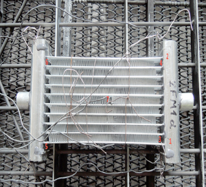
Fig. 1: The assembled mock up with Data Pack thermocouples just before brazing
Materials used in experiment:
- Flux: NOCOLOK® Zn Flux – 91.7% weight, lithium cryolite – 8.3% weight
- Fins: HA 3968-K
- Headers: HA 3905-R
- Tubes, alloy 1: HA 9108
- Tubes, alloy 2: HA 9170, both alloys coated on industrial machine (SAPA Precision Tubing) with NOCOLOK®ZnLi, load (8 and 16g/m2)
The fins, tubes and headers were manufactured by Hydro Aluminium Rolled Products.
Brazing of the mock ups was performed in industrial Active Only brazing line made by Seco/Warwick. As measured by Data Pack®, the parts stayed at temperature over 580°C for about 5 minutes.
After brazing the Zn diffusion profile and resistance to the so called soaking test were evaluated.
3 Results and discussion
Mock up experiment
Zn diffusion profiles was measured by X-ray microprobe JXA 8230 made by JEOL. Applied accelerating voltage: 15kV with the beam current 30nA. They were measured in two characteristic places: through the fin to tube joint and through the tube in the middle of the fin joints. This is shown in Fig. 2:


Fig. 2: Electron Back Scattered Image – example showing location of the analyses lines
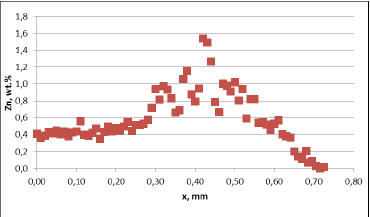
Fig. 3a: Zn diffusion profiles – as measured on the brazed mock ups, Diffusion profile across the joint, Flux load 8g/m2, tube alloy HA9180
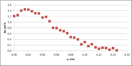
Fig. 3a: Zn diffusion profiles – as measured on the brazed mock ups, Diffusion profile between the joints, Flux load 8g/m2, tube alloy HA9180
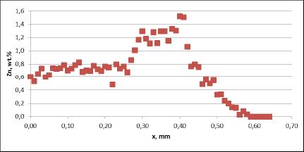
Fig. 3a: Zn diffusion profiles – as measured on the brazed mock ups, Diffusion profile across the joints, Flux load 16g/m2, tube alloy HA9170
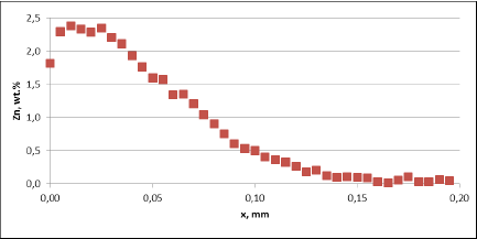
Fig. 3a: Zn diffusion profiles – as measured on the brazed mock ups, Diffusion profile between the joints, Flux load 16g/m2, tube alloy HA9170
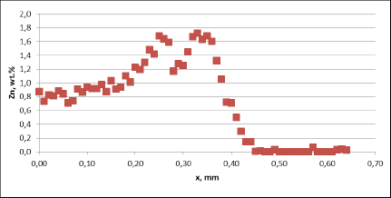
Fig. 3b: Zn diffusion profiles – as measured on the commercial sample, Spot 1, Diffusion profile across the joint
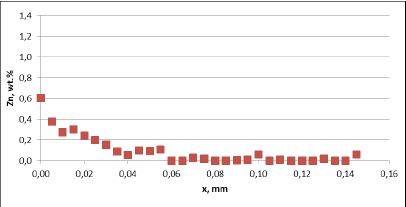
Fig. 3b: Zn diffusion profiles – as measured on the commercial sample, Spot 1, Diffusion profile between the joint
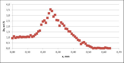
Fig. 3b: Zn diffusion profiles – as measured on the commercial sample, Spot 2, Diffusion profile across the joint
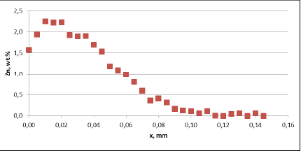
Fig. 3b: Zn diffusion profiles – as measured on the commercial sample, Spot 2, Diffusion profile between the joint
For all mock up samples the depth of diffusion profiles is around 120 microns. The maximum level of Zn concentration for lower flux load is at the range of 1.2% to 1.4% – and for higher flux load is in the range of 2.5%. These values seem to be typical for tubes coated with NOCOLOK®Zn Flux. Also the maximum content of Zn in the fillet seems to be rather well balanced with the Zn concentration on the tube surface (Fig. 3a).
For comparison, the diffusion profile of a commercial part was also investigated. In this case the diffusion profiles show quite significant differences – both in the depth of diffusion and the maximum Zn concentration on the tube surface. Also the Zn concentration is higher for fin to tube joint (Fig. 3b). This observation seems to be consistent with a well known fact that electric arc Zn coating is not uniform having places with high and low zinc load.
Literature
[1] A. Gray, H.W. Swidersky, L. Orman.
Reactive Zn Flux – an opportunity for controlled Zn diffusion and improved corrosion resistance. AFC Holcroft 11thInternational Invitational Brazing Seminar, October 2006
[2] A. Gray, A. Afseth, H.W. Swidersky. The influence of residual flux level on the corrosion behavior of heat exchanger materials, ASST, May 2003
[3] Solvay Patent. WO10060869 A1 – Anti-Corrosive Flux – NOCOLOK®Li Flux, 2010
[4] Solvay Patent. WO11098120 A1 – Flux Forming an Insoluble Brazing Residue – Li Flux – Li3AlF6, 2011
[5] NOCOLOK®Li Flux New Brazing Flux with Improved Residue Performance
Brazing aluminum products such as radiators, condensers, evaporators, etc. for the auto industry is a mass production process. The brazing operation is generally carried out in a mesh belt furnace under a nitrogen atmosphere and is commonly known as ‘CAB’ – Controlled Atmosphere Brazing.
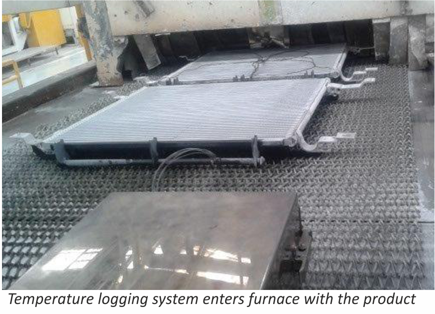
Accurate temperature measurement of the product throughout the furnace can be critical. Using a ‘through furnace’ temperature profiling system to measure product temperature is common practice within the industry, and the benefits are well established. There are also some known disadvantages to using these types of systems and here we look at recent developments to overcome these problems.
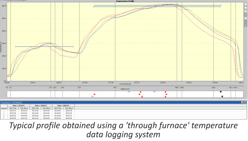
The ‘through furnace’ profiling system measures temperature by connecting thermocouples at specific points on the product which feed temperature information back to the data logger. The data logger is protected from the heat of the furnace by a ‘hot box’ or thermal barrier, allowing the system to travel through the furnace together with the product, storing valuable temperature data which is analysed at the end of the process using specialized software.
As previously stated the benefits of using temperature profiling systems are well known, however there are some disadvantages, these are:
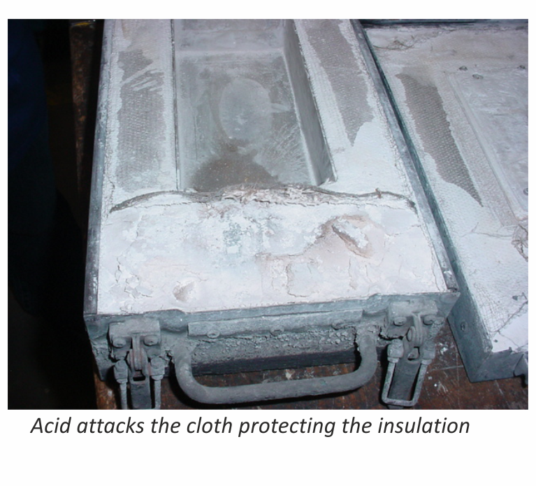
- The thermal barrier normally has a very limited life span as parts of the insulation package are subject to acid attack from chemicals within the flux.
- Oxygen can leak from within the thermal barrier while it is in the furnace, potentially contaminating the nitrogen atmosphere.
A. Acid attack
During the braze cycle, moisture in the air inside the ‘hot box’ or thermal barrier will combine with chemicals in the brazing flux to form hydrofluoric acid which attacks the high temperature cloth covering the microporous insulation. Once this cloth begins to break down, the unprotected insulation at the entrance to the ‘hot box’ wears away increasing the aperture where the thermocouples enter. This allows heat in, potentially damaging the data logger, and lets oxygen escape into the furnace atmosphere, which may affect braze quality.
The life of this type of thermal barrier is severely reduced leading to high maintenance costs. The solution uses a robust ‘drawer’ design rather than the traditional ‘clam shell’ type.
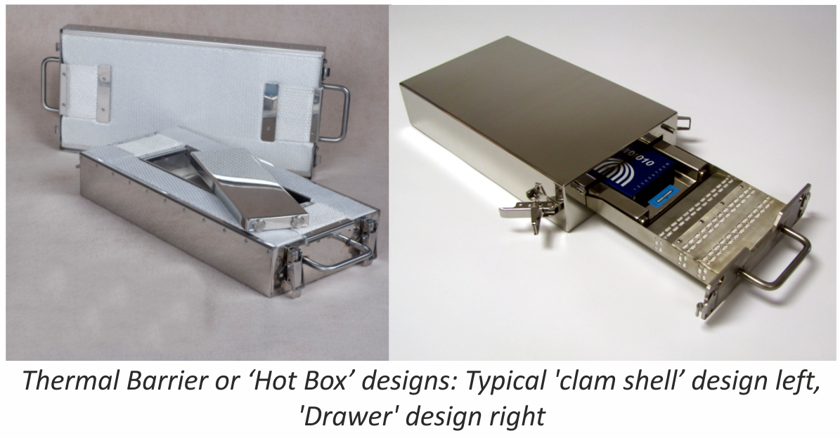
This eliminates exposure of the high temperature cloth to the aggressive flux atmosphere, and significantly increases the life of the barrier. This new type of thermal barrier has been used in daily production since April 2011 at many leading automotive parts suppliers, with one major North American auto manufacturer reporting over two thousand uses without any wear problems.
B. Oxygen leakage
Whether the thermal barrier is a ‘clam shell’ or ‘drawer’ type it will contain air. As the system travels through the furnace the air begins to warm up and expands. As it expands it begins to leak out into the furnace atmosphere, which may be an issue to some users.
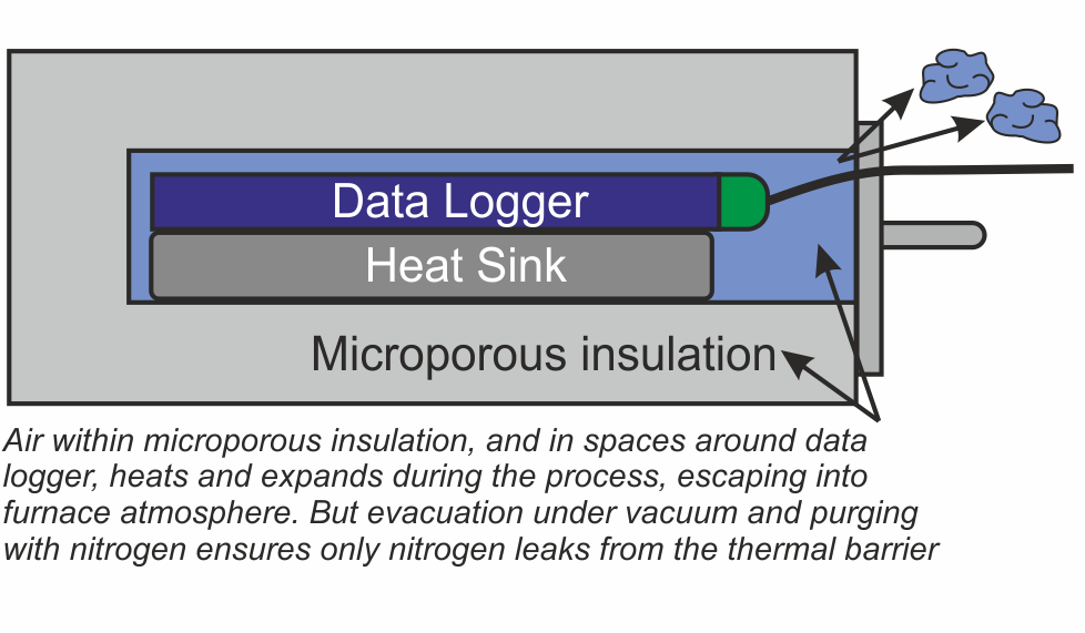
There are two areas within the thermal barrier where air will accumulate – within the microporous insulation, and in the spaces around the data logger and heat sink. A ‘two stage’ approach has been developed to remove this air.
Firstly eliminating the air deep within the microporous insulation is achieved by heating the whole thermal barrier or ‘hot box’ in a high vacuum, then back filling with nitrogen. This operation is carried out as the last stage in the manufacturing process.
Secondly, as an option for users with sensitive processes, all remaining air in the spaces around the data logger can be purged with low pressure nitrogen just prior to placing the system in the brazing furnace.
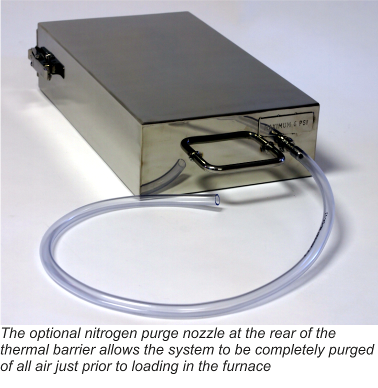
The nozzle for the nitrogen purge has been designed to allow free flow of the gas through the barrier, but by use of strategically placed internal ‘baffles’, heat penetration is minimized during the brazing process.
Conclusion
Although using a profiling system to monitor the product temperature in a CAB furnace has generally been considered high maintenance, it was judged that the value of the data obtained was worth the extra cost. However through careful system design a solution has been engineered that successfully overcomes these problems, saving maintenance costs and allowing the ‘hot box’ temperature profiling system to be used on a more regular basis.
Dave Plester, Director
Phoenix Temperature Measurement
www.phoenixtm.com
sales@phoenixtm.com
Approach to non-corrosive fluxes for further reduced residue solubility and improved magnesium tolerance
Technical Information by Ulrich Seseke-Koyro, Hans-Walter Swidersky, Leszek Orman, Andreas Becker, Alfred Ottmann
We split the article in four parts:
- Abstract and Basic Experimental Laboratory Procedures
- Reduced Flux Residue Solubility
- Improved Magnesium Tolerance
- Summary and Outlook
Summary
Our research activities so far have been focusing on flux blends with additives to validate lower water solubility of post braze flux residue. Another objective of this work was to allow for brazing of Al alloys with increased Mg levels using non corrosive fluxes.
First steps have been made with selected flux blends. This paper reflects the current project status, but more work still needs to be done for further improvement.
Low flux residue solubility
It has been shown that the flux residue water solubility is reduced by combining KAlF4 with AEFs (“KAlF4 compound concept”); among them BaF2 being the most promising candidate.
Fluxes for higher Mg tolerance
Flux blends containing KAlF4 plus CsAlF4 and Li3AlF6 seem to be a promising approach to improve brazing of higher Mg containing aluminium alloys.
Aluminium coupons samples (AMAG 6951 with 0.68% Mg) for the base coupon and the angle (1.36% Mg in the joint interface) require flux loads as high as 15g/m2 for successful brazing.
Good joint formation can be achieved at 5g/m2 load on samples with 0.68% Mg content. Thus brazing of higher Mg level Al-alloys with appropriate flux mixtures at process-typical loads seems to be feasible.
Outlook
For the continuation of this project, we need to define the Mg range for real industrial aluminium heat exchanger needs. We think that this can best be done in a joint effort of HX manufacturer, Al material supplier and flux producer.
- P Garcia et al, Solubility Characteristics of Potassium Fluoroaluminate Flux and Residues, 2nd Int. Alum. Congress HVAC&R, Dusseldorf (2011)
- P Garcia et al., Solubility and Hydrolysis of Fluoroaluminates in Post-Braze Flux Residue, 13th AFC Holcroft Invitational Aluminum Brazing Seminar, Novi (2008)
- J Garcia et al, Brazeability of Aluminium Alloys Containing Magnesium by CAB Process Using Cs Flux, VTMS5, 2001-01-1763 (2001)
- H Johannson et al, Controlled Atmosphere Brazing of Heat Treatable Alloys With Cesium Flux, VTMS6 C599/03/2003 (2003)
- Handbook of Chemistry and Physics; Ref. BaSO4: 0.0025 g/l
- U Seseke, Structure and Effect – Mechanism of Flux Containing Cesium, 2nd Int. Alum. Brazing Con., Düsseldorf (2002)
Approach to non-corrosive fluxes for further reduced residue solubility and improved magnesium tolerance
Technical Information by Ulrich Seseke-Koyro, Hans-Walter Swidersky, Leszek Orman, Andreas Becker, Alfred Ottmann
We split the article in four parts:
- Abstract and Basic Experimental Laboratory Procedures
- Reduced Flux Residue Solubility
- Improved Magnesium Tolerance
- Summary and Outlook
Improved Magnesium tolerance
Mg additions to Al alloys contribute to higher strength properties. The ongoing trend in saving weight by down-gauging of Al sheet thickness requires sufficient mechanical stability. One option for the production of higher strength Al alloys is to increase the Mg content.
A disadvantage of Mg is the interaction with potas-sium fluoroamuminate fluxes during brazing, which results in poor joint formation [3] [4]. This effect, known as “flux poisoning”, is caused by the formation of high melting compounds. The addition of caesium and other metals to the flux helps to compensate to a certain degree the poisoning [6].
For the first set of laboratory brazing experiments we chose commercially available AMAG 6951 brazing sheet (0.68% Mg, 4343 clad) and clad-less AMAG angle material (0.68% Mg) to investigate the brazing performance and joint formation. In this situation the metal-to-metal interface adds up to 1.36% Mg (2 x 0.68%) in total.
Table 1 shows a list of representative flux combina-tions with NOCOLOK® types, KAlF4, Li3AlF6. CsAlF4, and AEFs.
We repeated all brazing tests with each sample three times.
| Flux Type | Load | Fillet visual validation | Comment |
|---|---|---|---|
| NOCOLOK® Cs Flux | 10 g/m2 | 100% | very small joint inconsistent seam |
| MD001212 LiCs24 | 10 g/m2 | 100% | small joint weak seam |
| MD001223 LiCs43 | 10 g/m2 | 86% | small joint inconsistent seam |
| AB039215 KAlF4/BaF2 | 10 g/m2 | 52% | small joint inconsistent seam |
| NOCOLOK® Cs Flux | 15 g/m2 | 100% | weak seam |
| MD001212 LiCs24 | 15 g/m2 | 100% | thicker than with NOC Cs Flux |
| MD001223 LiCs43 | 15 g/m2 | 100% | thicker than with NOC Cs Flux |
| AB039215 KAlF4/BaF2 | 15 g/m2 | 98% | weak seam slighly better than NOC Cs Flux |
Table 1: Brazing trials: AMAG clad – AMAG clad-free angle different flux blends based on KAlF4 plus BaF2/Li3AlF6/CsAlF4
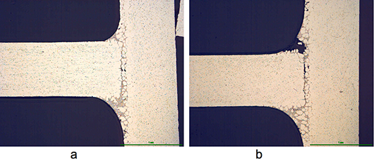
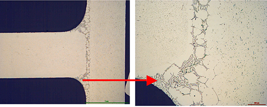
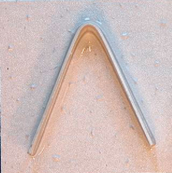
The angles from most of the AMAG specimens could be removed after brazing by pulling. Only a broken inner and outer fractured seam line was left – as can be seen below in picture 1 a.
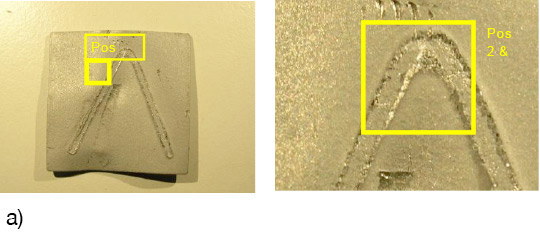
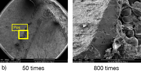
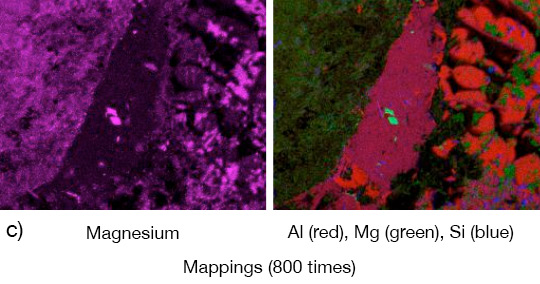
Picture 1: a) Photos, b) and c) SEM/EDX of NOCOLK® Cs Flux brazed sample (load 15 g/m²) Coupon 0.68% Mg, angle 0.68% Mg – angle removed by pulling
From the SEM analysis it is evident that a proper met-allurgical joint between base and angle has not been formed.
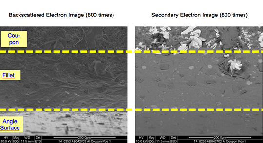
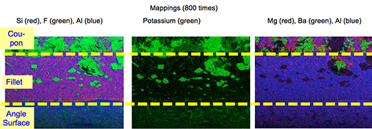
Picture 2: SEM/EDX analysis of aluminium ‘angle on coupon‘ brazed with KAlF4/BaF2 blend
There is flux residue present in the pulled apart fillet. This indicates that the liquid filler alloy was not capa-ble of pushing out completely the flux of the joint and it could be an explanation for the weakness of the fillet.
However, in case of the blend MD001212 LiCs24 with load 15g/m2 the joint structure is thorough as can be seen in picture 3 a).
Picture 3: Microstructures of the brazed joints
a) Flux MD001212, load 15g/m2
b) Flux MD001223, load 15g/m2
It is worth mentioning when connecting blocks are brazed to condenser manifolds often a high load of manually applied flux is used in order to overcome the high Mg content in the block material. For such a case using the mixture MD001212 would allow for having quite high Mg content in the block material, which can be required by the designers of condens-ers.
The total concentration of 1.36% Mg (joint interface) is probably too high, because for most brazing applica-tions, a flux load of 15g/m2 is impractical. Thus, we decided to reduce the level of Mg in our samples to half – i.e. to 0.68% – by switching to an AA1050 (Al 99.5%) angle. We also reduced the flux load to a more process-typical level of 5g/m². The results are listed in table 2:
| Flux Type | Load | Fillet visual validation | Comment |
|---|---|---|---|
| MD001212 LiCs24 | 5 g/m2 | 100% | good seam |
| NOCOLOK® Cs | 5 g/m2 | 87% | small joint |
Table 2: Brazing tests AMAG coupon (0.68% Mg)/Al99.5 angle
The structure of the joint cross section below (picture 4) obtained with flux MD001212 LiCs24 shows good quality.
Picture 4:Joint cross sections of alloys containing 0.68% Mg brazed with MD001212 LiCs24, load 5g/m2
To be continued…
- P Garcia et al, Solubility Characteristics of Potassium Fluoroaluminate Flux and Residues, 2nd Int. Alum. Congress HVAC&R, Dusseldorf (2011)
- P Garcia et al., Solubility and Hydrolysis of Fluoroaluminates in Post-Braze Flux Residue, 13th AFC Holcroft Invitational Aluminum Brazing Seminar, Novi (2008)
- J Garcia et al, Brazeability of Aluminium Alloys Containing Magnesium by CAB Process Using Cs Flux, VTMS5, 2001-01-1763 (2001)
- H Johannson et al, Controlled Atmosphere Brazing of Heat Treatable Alloys With Cesium Flux, VTMS6 C599/03/2003 (2003)
- Handbook of Chemistry and Physics; Ref. BaSO4: 0.0025 g/l
- U Seseke, Structure and Effect – Mechanism of Flux Containing Cesium, 2nd Int. Alum. Brazing Con., Düsseldorf (2002)
Approach to non-corrosive fluxes for further reduced residue solubility and improved magnesium tolerance
Technical Information by Ulrich Seseke-Koyro, Hans-Walter Swidersky, Leszek Orman, Andreas Becker, Alfred Ottmann
We split the article in four parts:
- Abstract and Basic Experimental Laboratory Procedures
- Reduced Flux Residue Solubility
- Improved Magnesium Tolerance
- Summary and Outlook
Reduced Flux Residue Solubility
The water solubility of standard NOCOLOK® Flux is 4.5 g/l, whereas for post-braze flux residue (pbr) it is 2.7 g/l. Post-braze residue of NOCOLOK® Li Flux shows a solubility of 2.2 g/l [1].
In the periodic table of chemical elements the group I fluorides have a reasonable low solubility (LiF: 2.7g/l [20°C]), but their Al-F-complexes much lower (Li3AlF6: 1.1g/l , K2LiAlF6: 0.3g/l with about 183 mg F-/l, K3AlF6: 2g/l), the group II fluorides (Alkaline Earth Fluorides “AEF”) show very low solubility (MgF2: 0.13g/l, CaF2: 0.016g/l, SrF2: 0.12g/l [25°C], BaF2: 0.12g/l [25°C]) [5]. Based on the facts of the dissolution behaviour of NOCOLOK® Li and the much lower solubility of the AEFs, we started investigating combinations of potas-sium fluoroaluminate fluxes with selected AEFs to combine the brazing characteristics of NOCOLOK® type flux with the very low solubility of AEF.
NOCOLOK® Flux consists of potassium fluoroalumi-nates with a specific ratio of KAlF4 and K2AlF5. Each of these compounds has different solubility. The combination of the (pure) compounds with different AEFs was of our main interest. We melted and pulverized the flux blends, dissolved them in a defined amount of DI-water and analyzed for K, Al and F.
The data achieved form these experiments is illus-trated in figure 1:
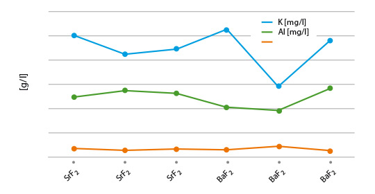
Fig. 1: Solubility of flux blends – melted and pulverized
(lines are used to illustrate differences of the blends)
Considering minor statistical variations, the results look quite reasonable, with the blend of NOCOLOK® Li/BaF2 showing the lowest K value. This observation can be explained by the low solubility of NOCOLOK® Li Flux. Of more relevance is the actual post-braze solubility (flux residue) on brazed Al surfaces. Interactions of base material and molten filler metal may have a more complex chemical impact on the solubility behaviour
The results from coupon brazing under laboratory conditions and the solubility of the flux residue can be seen in figure 2.
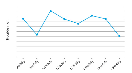
Fig. 2: Post-braze fluoride solubility of selected flux/ AEF combinations on Al coupons
(lines are used to illustrate differences of the blends)
Among the combination of NOCOLOK® type fluxes with diverse AEF additions, KAlF4/BaF2 shows the lowest residue F– solubility, i.e. 4mg/l. All our laboratory brazing tests with the samples showed the same good results like with standard NOCOLOK® Flux.
Corrosion comparison tests will be subject for future investigations.
To be continued…
- P Garcia et al, Solubility Characteristics of Potassium Fluoroaluminate Flux and Residues, 2nd Int. Alum. Congress HVAC&R, Dusseldorf (2011)
- P Garcia et al., Solubility and Hydrolysis of Fluoroaluminates in Post-Braze Flux Residue, 13th AFC Holcroft Invitational Aluminum Brazing Seminar, Novi (2008)
- J Garcia et al, Brazeability of Aluminium Alloys Containing Magnesium by CAB Process Using Cs Flux, VTMS5, 2001-01-1763 (2001)
- H Johannson et al, Controlled Atmosphere Brazing of Heat Treatable Alloys With Cesium Flux, VTMS6 C599/03/2003 (2003)
- Handbook of Chemistry and Physics; Ref. BaSO4: 0.0025 g/l
- U Seseke, Structure and Effect – Mechanism of Flux Containing Cesium, 2nd Int. Alum. Brazing Con., Düsseldorf (2002)
Approach to non-corrosive fluxes for further reduced residue solubility and improved magnesium tolerance
Technical Information by Ulrich Seseke-Koyro, Hans-Walter Swidersky, Leszek Orman, Andreas Becker, Alfred Ottmann
We split the article in four parts:
- Abstract and Basic Experimental Laboratory Procedures
- Reduced Flux Residue Solubility
- Improved Magnesium Tolerance
- Summary and Outlook
Abstract
For more than 30 years, potassium fluoroaluminates (NOCOLOK®) fluxes are already successfully used in controlled atmosphere brazing (CAB) of aluminium heat exchangers. Residues of these so-called non-corrosive fluxes have very low – but evident – solubility in water [1] [2]. In the discussion about corrosion of CAB produced aluminium heat exchangers, the flux residue solubility is an important parameter. There are concerns that – in addition to several other factors – fluoride ions (F–) potentially released from dissolved residue play a role in aluminium corrosion.
A theoretical option to address this point is the development of virtually insoluble flux. More realistic, however, will be fluxes with less soluble residues than the current compositions.
Some commercialised NOCOLOK® derivates, like NOCOLOK® Li Flux show already reduced solubility when compared to the standard product [1]. While investigating the chemical possibilities for further minimising the residue solubility and the release of F- ions, we have developed NOCOLOK® variants in combination with selected inorganic fluorides.
During this R&D project we also looked closely at the brazing properties of the new fluxes – with a focus on their performance for brazing of aluminium alloys with higher magnesium level. The current maximum magnesium range suitable for CAB with standard NOCOLOK® Flux is approximately 0.3%. Some improvement can be seen when using caesium-containing NOCOLOK® formulations (up to 0.5% Mg) [3] [4]. Some of the new fluxes we developed for further reduced residue solubility surprisingly show higher magnesium tolerance. This article summarizes the results of our laboratory work related to the development of fluxes with further reduced residue fluorides solubility and improved magnesium tolerance.
Basic experimental laboratory procedures
1. Lab brazing and alloy specimen setup
For experimental lab furnace brazing we used standard CAB brazing profile and 25 by 25 mm clad sheet coupons (single side) with angle on top. In case of the Mg topic an AMAG (Austria Metal AG) clad alloy (6951/4343) was brazed with an AMAG clad-less angle. Fluxing was done manually (flux load weight on precision scale, drops of isopropanol and homogenous spreading).
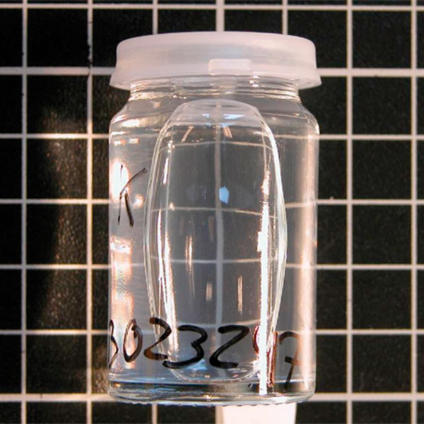
2. Solubility data generation
Coupon (3003/4343) with Al angle (Al 99.5%) were manually coated with a dedicated amount of flux blend and brazed as described in point 1. Brazed samples were placed in PET bottles and a defined quantity of demineralised water was added. Daily visual control and air exposure (by opening and closing the lid) was done.
To be continued…
- P Garcia et al, Solubility Characteristics of Potassium Fluoroaluminate Flux and Residues, 2nd Int. Alum. Congress HVAC&R, Dusseldorf (2011)
- P Garcia et al., Solubility and Hydrolysis of Fluoroaluminates in Post-Braze Flux Residue, 13th AFC Holcroft Invitational Aluminum Brazing Seminar, Novi (2008)
- J Garcia et al, Brazeability of Aluminium Alloys Containing Magnesium by CAB Process Using Cs Flux, VTMS5, 2001-01-1763 (2001)
- H Johannson et al, Controlled Atmosphere Brazing of Heat Treatable Alloys With Cesium Flux, VTMS6 C599/03/2003 (2003)
- Handbook of Chemistry and Physics; Ref. BaSO4: 0.0025 g/l
- U Seseke, Structure and Effect – Mechanism of Flux Containing Cesium, 2nd Int. Alum. Brazing Con., Düsseldorf (2002)
Additional information to the Article Flux Application: Electrostatic Fluxing
In dry flux application, the flux powder is electrostatically charged (typical voltage is ~ 100 kV) and applied to a grounded work piece. An electrical field results in flux deposition of the work piece. In practice, anisotropic distribution of the electric field can influence the homogeneity of powder coverage. At edges powder may accumulate, while penetration of powder into deep/thick fin packages (e.g., in case of double row tubes) can be limited by the Faraday cage effect.
Flux powder is electrically charged in the gun. However, it loses charge relatively fast when it hits the grounded heat exchanger. Therefore adhesion of the flux on the work piece is established rather by relatively weak Van der Waals forces than by electrostatic forces. Fine flux particles adhere better on the surface – but they are more difficult to operate with in the dry powder feeding system.
The relatively fine flux particles are more difficult to handle in dry powder feed systems compared to coarser paint powders – therefore the equipment used for electrostatic flux application is adapted to meet the specific requirements. Venturi pump, hose diameter, air flow and spray nozzle suitable for flux application are designed to minimize the possibility for powder buildup and clogging in the system. Powder transport within the hose system and the spray nozzle is further enhanced by introduction of additional air streams. The direction of the powder flow should always be from top to bottom. Sharp changes in flow direction must be avoided. In critical areas additional vibration units are installed to avoid powder buildup.
There are two types of powder feed systems established on the market (see the illustrations in the article):
The first type starts with the flux powder being fluidized in a fluidization vessel by compressed air that is fed through a porous membrane at the bottom of the fluidization vessel. The air going through the flux makes it behave like a fluid, since the powder is essentially diluted with air. A pick up tube attached to a Venturi pump is extended into the fluidized flux. Powder dosage is controlled by the volume of air flow through the pump. To optimize fluidization the vessel may additionally be equipped with a stirrer.
This type of feed system works perfectly well for classic electrostatic paints powders that are easy to fluidize, however, it may be difficult to establish a stable fluidization with ’standard‘ flux powder (i.e. the flux powder quality offered for wet/slurry-based flux application).
Fluctuations in density of the fluidized bed can result in inhomogeneous spray pattern (splashing) and might be a source for flux buildup within the system.
NOCOLOK® Flux Drystatic is optimized to minimize the challenges of powder feeding, while providing sufficient fine particle fraction for good adhesion properties.
The second type of powder feed system works on the principle of feeding the powder by a rotating helix screw (see the illustrations in the article above). Because of the mechanical displacement of the flux powder from the hopper, such devices minimize fluctuations of flux powder flow.
Most mechanical type of dry flux feed systems work with standard quality NOCOLOK® Flux as well as with special ‚Drystatic‘ grade NOCOLOK® powder.
To achieve flux distribution patterns for specific process needs (e.g., higher flux loads in tube to header areas, coating from both sides of thick cores), multiple spray nozzles are arranged for deposition of the necessary flux load at different locations of the heat exchanger.
Dry fluxing booths must be equipped with a filter system to collect the overspray. The overspray material is recycled within the booth. To avoid accumulation of impurities within the recovered flux, it is necessary to take care of the booth environment (i.e. avoid dust, fumes, and high humidity level) as well as for the quality of the compressed air used. Contamination introduced by the heat exchangers or the transport belt must be prevented as well.
Due to the relatively weak flux adhesion (compared with wet- or paint- application methods), handling of dry fluxed parts should be done with special care to avoid flux fall off, especially at higher flux loads. To reduce flux fall off, some users perform electrostatic fluxing on heat exchangers with evaporative oils still present on the surfaces. Thermal degreasing in this case takes place after fluxing – just before the parts enter the brazing furnace.