Schlagwortarchiv für: Flux Load

HF can potentially be formed during the flux brazing process. HF is very toxic, irritating to the eyes, skin and respiratory tract and cause severe burns of the skin and eyes. The threshold limit value (TLV) for HF is a ceiling concentration of 3 ppm (2.3 mg/m3), a concentration that should not be exceeded during any part of the working shift.

Drying ovens can be electrically heated or gas fired. In gas fired drying ovens, it is possible that any flux particles entrained in the moist air and passed through the high temperature flames may generate HF. The concern here is not so much with employee exposure, but that HF may be released into the atmosphere.

Similarly, flux particles coming in contact with the hot flames in a flame brazing station may also generate HF. Suitable local exhaust systems must be in place to capture vapors and fumes that may contain HF.

It is known that one of the components of the flux, KAlF4, has a measurable vapor pressure and the rate of evaporation increases rapidly once the flux is molten. With regard to CAB brazing (furnace brazing) where traces of moisture are always present even at below –40°C dew point, a number of compounds can be formed in the system K – Al – F – H – O. To our knowledge there has been no academic effort to create a thermodynamic model of this system. Thus, it is impossible to predict which compounds will and will not exist, and in what temperature or humidity regimes. This is why more than one mechanism has been proposed for the generation of HF, but no unique reaction mechanism has been identified:
3KAlF4 + 3H2O → Al2O3 + K3AlF6 + 6HF
2KAlF4 + 3H2O → 2KF + Al2O3 + 6HF

While the evidence above points to gas phase reactions between flux fumes and water vapor for the generation of HF, Thompson and Goad1) proposed that AlF3 dissolved in the flux melt is subject to hydrolysis according to:

2AlF3 + 3H2O → Al2O3 + 6HF

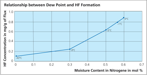
What is clear is that in all cases, HF is shown as a reaction product. As for the quantity, Field and Steward2) have indicated that the amount of HF formed is typically 20 ppm in the exhaust of a continuous tunnel furnace. Solvay’s own research work showed that even when flux on aluminum is heated in a bone-dry nitrogen atmosphere, a small quantity of HF is still generated3). A source of hydrogen must be made available for HF to be formed even under bone-dry conditions and this might include reduction of aluminum hydroxide, degassing of furnace walls, leakage or other less obvious sources. The work showed that even under ideal conditions, it is virtually impossible to avoid some HF formation. The graph below shows the relationship between dew point and HF formation:

The amount of HF generated depends on several factors such as:

  • Flux load going through the furnace – flux loading and component throughput
  • Temperature profile – heating rate and time at temperature
  • Furnace atmosphere conditions such as nitrogen flow and dew point

The HF is exhausted together with the nitrogen stream and absorbed by the dry scrubber.


1) Thompson, W.T., Goad, D.W.G., Can. J. Chem., 1976, Vol. 54, p3342-3349
2) Steward N.I., Field D.J., SAE 870186, 1987
3) Lauzon, D.C., Belt, H.J., Bentrup, U., Therm Alliance Seminar, Detroit, 1998


Very often, heat exchanger manufacturers increase the flux loading on components to be brazed to compensate for furnace atmosphere or other process related deficiencies. The flux is an excellent “band-aid” and can be used as such, but only while the true problems are located and rectified. Long term use of higher than recommended flux loads can lead to other problems.

Over fluxing causes more KAlF4 evaporation and condensation. This will load up the dry scrubber more quickly. White powder will accumulate more quickly on the curtains at the exit end of the furnace. If this is noticed, there is a very good chance that the dry scrubber is loading up more quickly.

There will be a more rapid build-up of the flux inside the furnace. This is a common issue with over fluxing whereby flux builds up on the muffle floor at the entrance to the cooling zone where it will solidify. This flux build up has been known to deflect the mesh belt.

There is more rapid build up of the flux on the fixtures which can significantly reduce maintenance intervals.

Over-fluxing can lead to visible flux residue on the brazed heat exchanger which may increase the incidence of flux residue fall-off. Excess flux residue dulls the appearance of a brazed heat exchanger and can also accumulate in the gasket areas causing problems with seals. Too much flux residue will also inhibit surface treatments such as painting or conversion treatments.

The theoretical amount of flux required to dissolve a 100 Å oxide film is about 0.02 g/m2
(1 Å = 10-10 m = 0,1 nm). For a 400 Å film, still only 0.08 g/m2 flux is required. These do not take into account losses to moisture, oxygen or poisoning of the flux by Mg alloy additions.

In practice however, the recommended loading for fluxing is 5 g/m2, uniformly distributed on all active brazing surfaces. This is more than 250 times the theoretical amount required for oxide dissolution. To visualize what 5 g/m2 flux loading might look like, think of a very dusty car. As the heat exchange manufacturer gains experience with his products, he may find that a little more is required for consistent brazing or that he can get away with a little less flux.

Too little flux will result in poor filler metal flow, poor joint formation, higher reject rates, and inconsistent brazing. In other words, the process becomes very sensitive.

Too much flux will not affect the brazing results. However there will be pooling of flux which can drip on the muffle floor, the surface of the brazed product will be gray and there will be visible signs of flux residue. Furthermore, flux will accumulate on fixtures more rapidly which then requires more frequent maintenance. More importantly yet, using too much flux will increase the process costs.

In some cases, heat exchanger manufacturers use higher than recommended flux loadings to mask furnace atmosphere deficiencies. This should be viewed as a short-term solution and the furnace problems should be addressed.

See also: How to evaluate flux load?

The following article provides some answers on general questions regarding the use of NOCOLOK Sil Flux for manufacturing pots and pans.

What is the NOCOLOK Sil Flux quantity (per m²) required for sandwich brazing or pressure cookers (stainless steel to aluminium)?
The recommended load for NOCOLOK Sil Flux is approximately 15 to 25 g/m². Brazing aluminium to stainless steel requires rapid processing, i.e. very fast heating ramp and short time at brazing temperature. Usually, this can only be accomplished with induction brazing.

When brazing aluminium to stainless steel using NOCOLOK Sil Flux, the Sil Flux first forms the filler metal from the aluminium component. The filler metal then reacts with the stainless steel to form a thin layer of FeAl3.

From a metallurgraphic point of view, there is a multi-layer system (microscopic structures). First, there is the stainless steel, then the layer of FeAl3, then the Al/Si filler metal, and finally the aluminium substrate. The FeAl3 layer is very brittle, and so it is important that this layer is kept as thin as possible. The thickness of this layer is a function of time and temperature,- consequently the need for a short brazing cycle.

Brazing of Stainless Steel with Aluminium

To prepare a NOCOLOK Sil Flux slurry or paste: What is the exact mixing ratio (flux to solvent) required?
The mixing ratio for NOCOLOK Sil Flux slurries or pasts depends on the application method on site. In some cases, the main focus is a specific viscosity for an automated fluxing system. In other cases, only small flux quantities are prepared for immediate consumption.

NOCOLOK Sil Flux can be prepared with alcohol (ethanol or isopropyl alcohol) or alcohol/ water mixtures (70% alcohol content) in any ratio from 20 to 60 wt% (solids). As mentioned earlier, the actual slurry concentration will depend on the application procedure. The objective is to achieve 15 to 25 g/m² surface area.

If the NOCOLOK Sil Flux slurry is not completely consumed within one or two days, we recommend using pure alcohol as carrier to avoid any chemical reaction between the solvent and the metal powder (silicon). Due to hydrolysis of the silicon powder, water should not be used to prepare NOCOLOK Sil Flux paste.

Brushing, dipping or spraying can be utilised to apply the flux. Uniformity of the applied flux coating is very important.

How fast after applying NOCOLOK Sil Flux, the components should be processed for best results?
Before the part is heated up, the NOCOLOK Sil Flux slurry or past coating on the component surfaces should be thoroughly dried or allowed to evaporate. If alcohol is used as a carrier, the evaporation will only take a few seconds (with 15 to 25 g/m² flux load). NOCOLOK Sil Flux is non hygroscopic (i.e. the flux does not attract and absorb moisture) and non-corrosive (i.e. there is no reaction between the flux and the metal surfaces at room temperature). If a water mixture is used as the flux carrier, the components must be dried after flux application to avoid water-based corrosion effects.

What is the grain/ particle size distribution of the silicon metal powder in NOCOLOK Sil Flux?

The silicon particles in NOCOLOK Sil Flux show a particle size distribution curve with most of the grains within a range of 10 to 45μm. The Solvay specification for NOCOLOK Sil Flux (fine grade) – which is used for brazing pots and pans – is as follows:
< 5μm: < 25%
10 to 20μm: 50%
> 35μm: < 10%
> 74μm: not detectable (by laser particle size analysis)

What are the key points regarding product fit-up for good joint formation in NOCOLOK Sil Flux technology?

During the brazing process it is important that the components to be joined are in intermediate contact with each other. There must be firm pressure applied on all the surfaces of the plates throughout the brazing cycle to avoid large voids and gaps. Filler metal can only fill gaps up to a certain width (i.e. approximately 0.10 to 0.15 mm).

How to measure?

In the case of heat exchangers, the surface area being fluxed must first be determined. For ease of calculation, the louvers on the fin can be ignored. The radius on the fin can also be ignored.

Imagine then the fin pulled out of the heat exchanger and straightened out to form one long strip. Similarly, the surface area of the slots in the header can also be ignored.

Remember that in calculating the surface area of the heat exchanger, there are 2 sides to every tube, 2 sides to every fin and 2 sides to the headers. The total surface area is then expressed in m2: All dimensions are in meters (m) to yield a surface area in square meters.

Header


Assuming it is a cylindrical (condenser) header:

SA (m2) = (2 x 3.14 x radius of header(m)) x length of header (m) x 2 headers

Assuming it is a radiator header:

SA (m2) = length of header (m) x width of header (m) x 2 (sides/header) x 2 (headers)

Tubes

SA(m2) = width of tube(m) x length of tube (m) x 2 (sides/tube) x total number of tubes

Fins

Ignore the louvers in the fins

SA (m2) = width of fin (m) x (fin height (m) x number of fin legs/tube) x 2 ( sides/fin) x total number of fins

Total Surface area in m2 = SA headers + SA tubes + SA fins

To determine the flux loading, a degreased and thoroughly dry heat exchanger is weighed. The heat exchanger is then run through the fluxer, blow-off and dry-off section of the furnace. The heat exchanger is removed just prior to entering the brazing furnace and weighed again.

The flux coating weight is then determined using the following formula:

Weight of unit fluxed and dried (g) – weight of unit un-fluxed (g) x Surface area (m2)

To make sure that the flux loading was determined on a completely dry unit, run it through the dry-off section a second time and re-weigh.

See also: Flux loading