Schlagwortarchiv für: Temperature

Brazing aluminum products such as radiators, condensers, evaporators, etc. for the auto industry is a mass production process. The brazing operation is generally carried out in a mesh belt furnace under a nitrogen atmosphere and is commonly known as ‘CAB’ – Controlled Atmosphere Brazing.
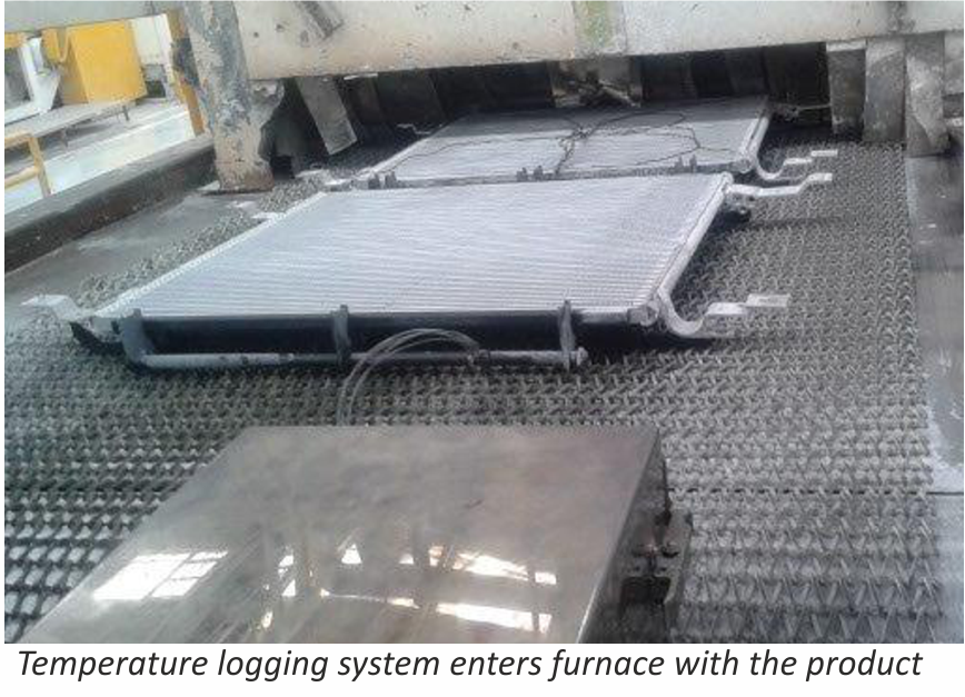
entering furnace 1

Accurate temperature measurement of the product throughout the furnace can be critical. Using a ‘through furnace’ temperature profiling system to measure product temperature is common practice within the industry, and the benefits are well established. There are also some known disadvantages to using these types of systems and here we look at recent developments to overcome these problems.
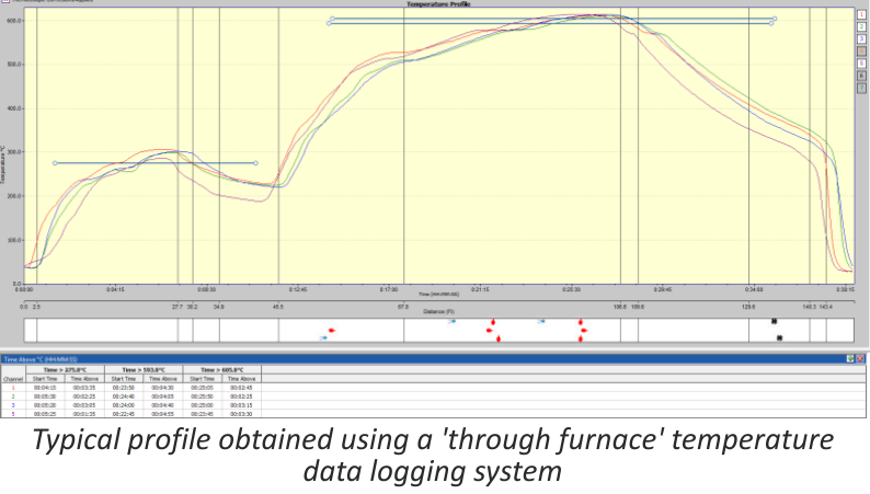
profile 2

The ‘through furnace’ profiling system measures temperature by connecting thermocouples at specific points on the product which feed temperature information back to the data logger. The data logger is protected from the heat of the furnace by a ‘hot box’ or thermal barrier, allowing the system to travel through the furnace together with the product, storing valuable temperature data which is analysed at the end of the process using specialized software.

As previously stated the benefits of using temperature profiling systems are well known, however there are some disadvantages, these are:

  1. The thermal barrier normally has a very limited life span as parts of the insulation package are subject to acid attack from chemicals within the flux.
  2. Oxygen can leak from within the thermal barrier while it is in the furnace, potentially contaminating the nitrogen atmosphere.

A. Acid attack

During the braze cycle, moisture in the air inside the ‘hot box’ or thermal barrier will combine with chemicals in the brazing flux to form hydrofluoric acid which attacks the high temperature cloth covering the microporous insulation. Once this cloth begins to break down, the unprotected insulation at the entrance to the ‘hot box’ wears away increasing the aperture where the thermocouples enter. This allows heat in, potentially damaging the data logger, and lets oxygen escape into the furnace atmosphere, which may affect braze quality.
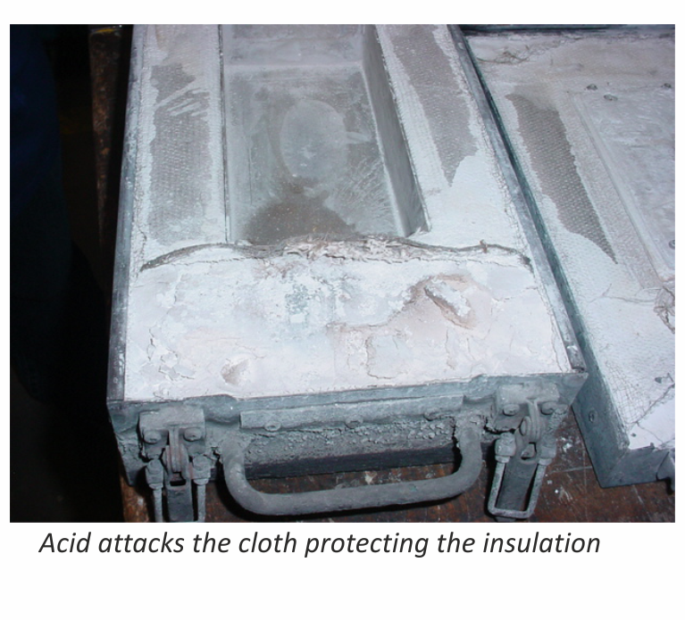
damage

The life of this type of thermal barrier is severely reduced leading to high maintenance costs. The solution uses a robust ‘drawer’ design rather than the traditional ‘clam shell’ type.
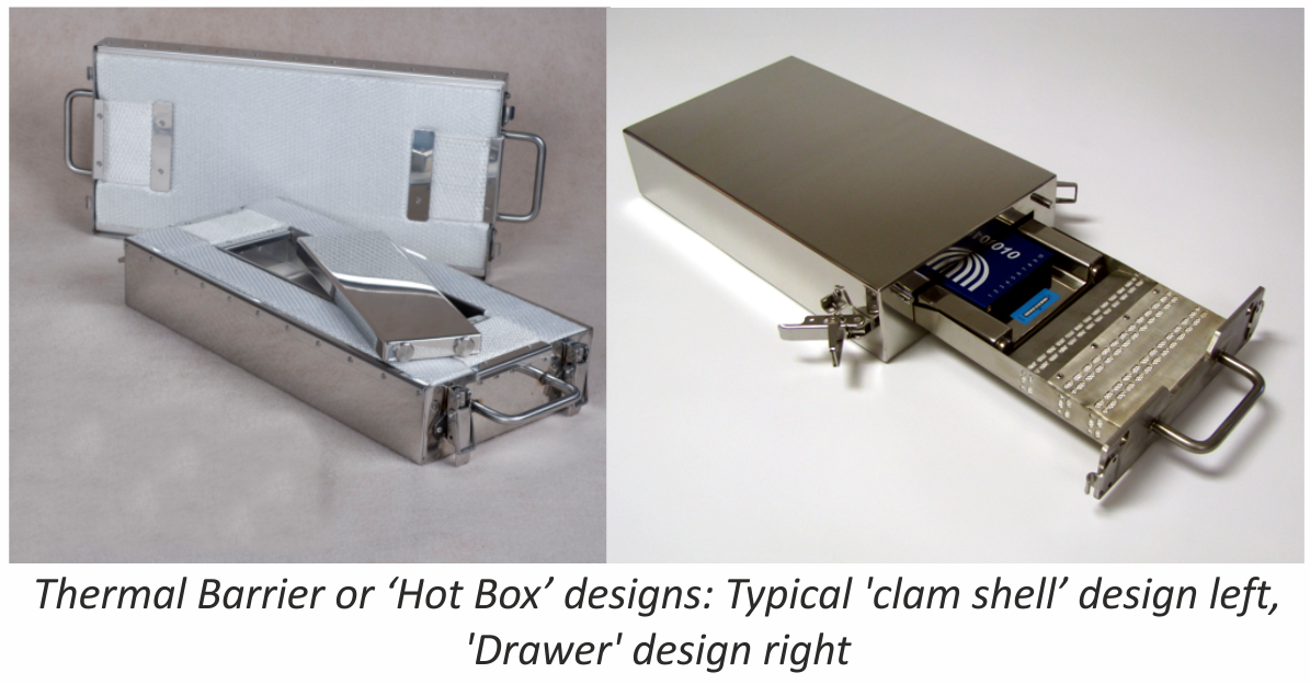
combination5

This eliminates exposure of the high temperature cloth to the aggressive flux atmosphere, and significantly increases the life of the barrier. This new type of thermal barrier has been used in daily production since April 2011 at many leading automotive parts suppliers, with one major North American auto manufacturer reporting over two thousand uses without any wear problems.

B. Oxygen leakage

Whether the thermal barrier is a ‘clam shell’ or ‘drawer’ type it will contain air. As the system travels through the furnace the air begins to warm up and expands. As it expands it begins to leak out into the furnace atmosphere, which may be an issue to some users.
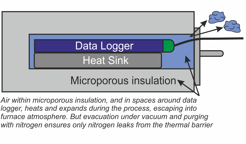
air in barrier4

There are two areas within the thermal barrier where air will accumulate – within the microporous insulation, and in the spaces around the data logger and heat sink. A ‘two stage’ approach has been developed to remove this air.

Firstly eliminating the air deep within the microporous insulation is achieved by heating the whole thermal barrier or ‘hot box’ in a high vacuum, then back filling with nitrogen. This operation is carried out as the last stage in the manufacturing process.

Secondly, as an option for users with sensitive processes, all remaining air in the spaces around the data logger can be purged with low pressure nitrogen just prior to placing the system in the brazing furnace.
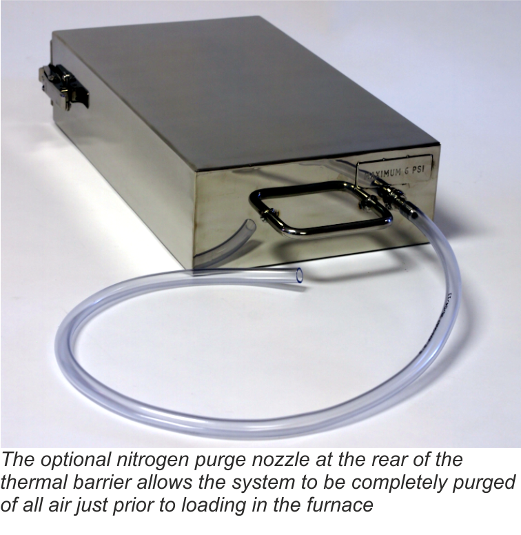
purge

The nozzle for the nitrogen purge has been designed to allow free flow of the gas through the barrier, but by use of strategically placed internal ‘baffles’, heat penetration is minimized during the brazing process.

Conclusion

Although using a profiling system to monitor the product temperature in a CAB furnace has generally been considered high maintenance, it was judged that the value of the data obtained was worth the extra cost. However through careful system design a solution has been engineered that successfully overcomes these problems, saving maintenance costs and allowing the ‘hot box’ temperature profiling system to be used on a more regular basis.

Dave Plester, Director
Phoenix Temperature Measurement
www.phoenixtm.com
sales@phoenixtm.com

Article from the Newsletter of our sponsor Solvay Fluor:
New glass brazing furnace in the NOCOLOK Technical Center

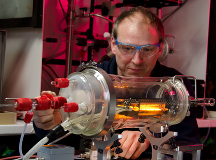
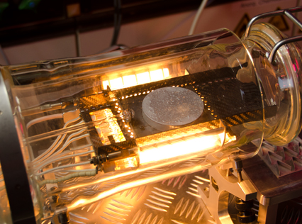
Many visitors to seminars, trade shows or videos are already familiar with the test glass brazing furnace in the NOCOLOK Technical Center. The unique furnace now has a big brother. All components of the new test furnace, except for the radiant heater, were developed in own production at Solvay.

The fluorine research workshop in Hannover has done an excellent job, “The construction of such a furnace is only possible with the tremendous expertise of the colleagues in the test workshop,” says Andreas Becker, a Solvay Fluor research employee. “With the new glass furnace, it is possible to braze larger objects, such as aluminium wafers for refrigerant test series for automobile producers.”

Specially developed software can capture every stage of the brazing process as high-resolution images – so that not even the tiniest detail of the brazing process can escape the testers. The new furnace saves energy and time – test brazing series with larger objects no longer require the much larger Camlaw brazing furnace at the Technical Center.

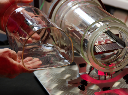
The next stage of development is already being planned: in a unique process Solvay’s glass blowers have succeeded in forming a square glass body, which offers even more space for larger items.

An overview of all services from the NOCOLOK Technical Center is offered in the new brochure, which is available for download.

HF can potentially be formed during the flux brazing process. HF is very toxic, irritating to the eyes, skin and respiratory tract and cause severe burns of the skin and eyes. The threshold limit value (TLV) for HF is a ceiling concentration of 3 ppm (2.3 mg/m3), a concentration that should not be exceeded during any part of the working shift.

Drying ovens can be electrically heated or gas fired. In gas fired drying ovens, it is possible that any flux particles entrained in the moist air and passed through the high temperature flames may generate HF. The concern here is not so much with employee exposure, but that HF may be released into the atmosphere.

Similarly, flux particles coming in contact with the hot flames in a flame brazing station may also generate HF. Suitable local exhaust systems must be in place to capture vapors and fumes that may contain HF.

It is known that one of the components of the flux, KAlF4, has a measurable vapor pressure and the rate of evaporation increases rapidly once the flux is molten. With regard to CAB brazing (furnace brazing) where traces of moisture are always present even at below –40°C dew point, a number of compounds can be formed in the system K – Al – F – H – O. To our knowledge there has been no academic effort to create a thermodynamic model of this system. Thus, it is impossible to predict which compounds will and will not exist, and in what temperature or humidity regimes. This is why more than one mechanism has been proposed for the generation of HF, but no unique reaction mechanism has been identified:
3KAlF4 + 3H2O → Al2O3 + K3AlF6 + 6HF
2KAlF4 + 3H2O → 2KF + Al2O3 + 6HF

While the evidence above points to gas phase reactions between flux fumes and water vapor for the generation of HF, Thompson and Goad1) proposed that AlF3 dissolved in the flux melt is subject to hydrolysis according to:

2AlF3 + 3H2O → Al2O3 + 6HF

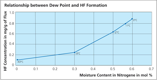
What is clear is that in all cases, HF is shown as a reaction product. As for the quantity, Field and Steward2) have indicated that the amount of HF formed is typically 20 ppm in the exhaust of a continuous tunnel furnace. Solvay’s own research work showed that even when flux on aluminum is heated in a bone-dry nitrogen atmosphere, a small quantity of HF is still generated3). A source of hydrogen must be made available for HF to be formed even under bone-dry conditions and this might include reduction of aluminum hydroxide, degassing of furnace walls, leakage or other less obvious sources. The work showed that even under ideal conditions, it is virtually impossible to avoid some HF formation. The graph below shows the relationship between dew point and HF formation:


The amount of HF generated depends on several factors such as:

  • Flux load going through the furnace – flux loading and component throughput
  • Temperature profile – heating rate and time at temperature
  • Furnace atmosphere conditions such as nitrogen flow and dew point

The HF is exhausted together with the nitrogen stream and absorbed by the dry scrubber.


1) Thompson, W.T., Goad, D.W.G., Can. J. Chem., 1976, Vol. 54, p3342-3349
2) Steward N.I., Field D.J., SAE 870186, 1987
3) Lauzon, D.C., Belt, H.J., Bentrup, U., Therm Alliance Seminar, Detroit, 1998

How to obtain?

A lot of information can be gained from heat exchanger brazing cycle temperature profile. It is probably one of the most important pieces of information that the brazing engineer can use to fully understand his process. A temperature profile will provide information such as heating rate, maximum peak brazing temperature, time at temperature, temperature uniformity across the heat exchanger and cooling rate. No other tool can provide so much information.

The simplest method for obtaining a temperature profile is to attach thermocouple wires to various parts of the heat exchanger and graphing the resulting profile on a chart recorder. The disadvantage of this method is that the thermocouple wire must be long enough to traverse the length of the furnace. One must also ensure that the wire does not become entangled in the mesh belt.

The second and more common (also more expensive) method of obtaining temperature profiles is with the use of a thermally insulated data pack. The data pack is a stand-alone unit capable of withstanding brazing temperatures. The thermocouples wired into the data pack are attached to various parts of the heat exchanger. The data pack then travels on the belt with the heat exchanger through the brazing furnace. At the end of the run, the data stored in the data pack is downloaded into a computer where graphs can be generated. The sophisticated software allows the user to determine quickly a number of parameters such as maximum temperature reached by each thermocouple.

Recent advances in thermal profiling allows getting information in real time. The thermally insulated data pack transmits data in real time from inside the brazing furnace to a computer situated outside the furnace using the latest radio telemetry technology. Changes to the furnace settings can now be seen instantly1.

Heating Rate

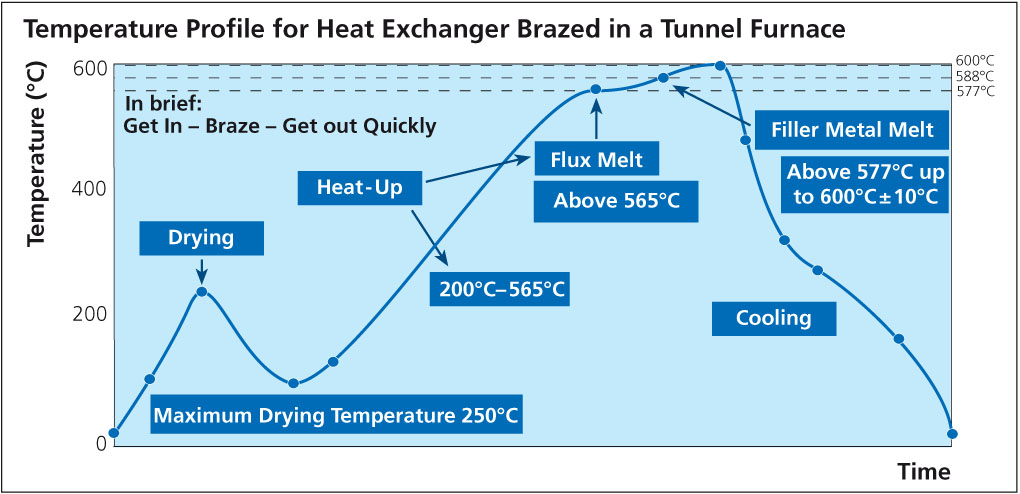
A minimum average heating rate of 20°C/min up to the maximum brazing temperature is recommended. With very large heat exchangers such as charge air coolers, lower heating rates may be used, but with higher flux loadings. Once the flux starts to melt, it also begins to dry out. With slower heating rates, it is possible that the flux can be sufficiently dry as to loose its effectiveness when the filler metal starts to melt or before the maximum brazing temperature is reached.

Heating rates up to 45°C/min in the range of 400°C to 600°C are not uncommon. One could say that the faster the heating the better. However, temperature uniformity across the heat exchanger must be maintained especially when approaching the maximum brazing temperature and this becomes increasingly more difficult with fast heating rates.

Maximum Brazing Temperature

For most alloy packages, the recommended maximum peak brazing temperature is anywhere from 595°C to 605°C and in most cases around 600°C.

Temperature Uniformity

During heat up, there may be quite a variation in temperature across the heat exchanger. The variation will tighten as the maximum temperature is reached. At brazing temperature it is recommended that the variation should not exceed ± 5°C. This can be difficult to maintain when larger units are processed which have differing mass areas within the product.

Time at Temperature

The brazed product should not remain at the maximum brazing temperature for any longer than 3 to 5 minutes. The reason is that a phenomenon known as filler metal erosion (core alloy dissolution / Silicon penetration into the base material) begins to take place as soon as the filler metal becomes molten. And so the longer the filler metal remains molten, the more severe the erosion is.

The graph below shows an actual temperature profile for a heat exchanger brazed in a tunnel furnace. One characteristic feature of all temperature profiles is where the curve flattens out when approaching the maximum peak brazing temperature (area shown in blue circle). The plateau in the temperature profile is associated with the start of melting of the filler metal at 577°C, known as the latent heat of fusion. It is called latent heat because there is no temperature change when going from solid to liquid, only a phase change.

Temperature profile for a heat exchanger brazed in a tunnel furnace.

1 D. Plester, Datapak Ltd., International Congress Aluminium Brazing, Düsseldorf (2002)

As manufactured, a non-corrosvie K-Al-F-type flux typically is a mixture of potassium tetra-fluoroaluminate (KAlF4), and also contains potassium penta-fluoroaluminate (K2AlF5). K2AlF5 exists in different modifications: potassium penta-fluoroaluminate hydrate (K2AlF5 · H2O), and hydrate-free (K2AlF5).
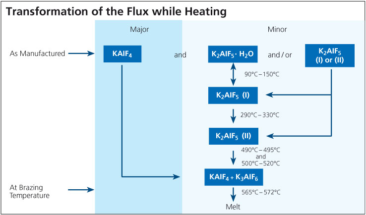
During the brazing process, the material undergoes essential physico-chemical alterations. While the chief component, KAlF4, is simply heated up, the compound K2AlF5 · H2O begins to lose its crystal water from 90°C (195°F) on. When the temperature is further increased within the ranges of 90° – 150°C (195°F – 302°F), and 290°C – 330°C (554°F – 626°F), two different crystallographic (structural) modifications of K2AlF5 are formatted.

When the furnace temperature is raised above 490°C (914°F), K2AlF5 begins to react chemically. According to the equation:

2 K2AlF5 → KAlF4 + K3AlF6 (Equation 1)

the exact amount of potassium hexa-fluoroaluminate (K3AlF6) necessary for a eutectic flux composition (i.e. mixture of two or more substances which has the lowest melting point; see phase diagram) is obtained from the original K2AlF5 content. At brazing temperature, the resulting flux composition has a clearly defined melting range of 565°C to 572°C (1049°F – 1062°F). The flux melts to a colorless liquid.
Due to a vapor pressure of 0.06 mbar at 600°C, some of the KAlF4 evaporates during the brazing cycle, particularly once melting temperature is reached. The total content of KAlF4 contained in the exhaust is depending on time and temperature. Based on results from TGA analysis (with a heating rate of 20°C/min), the quantity of volatile compounds in Flux between 250°C and 550°C (482°F and 1022°F) is approximately 0.2 to 0.5%. These flux fumes contain fluorides and have the potential to react with the furnace atmosphere, especially moisture, to form hydrogen fluoride according to the equation:

3 KAlF4 + 3 H2O → K3AlF6 + Al2O3 + 6 HF (Equation 2)

This is one of the reasons, why the brazing process should take place in a controlled atmosphere (nitrogen) with low dew point and low oxygen level (another reason is to minimize re-oxidization effects on the aluminum surfaces).

Directly after brazing has been completed, flux residues consist mainly of KAlF4 and K3AlF6. In the presence of moisture from the surrounding atmosphere, the K3AlF6 is converted back to K2AlF5 · H2O over time (several days) in a reaction reverse to the one described in equation 1 followed by a re-hydration step.

The schematic below illustrates the transformations that occur as the flux is heated to brazing temperature. Note that these phases are unstable outside the furnace atmosphere.

Process related causes

The service life of a heat exchanger may be shortened due to corrosion caused by process related events. Some examples are listed below:

Excessively high brazing temperature or too long time at temperature will lead to excessive Si diffusion in the core. Si diffuses along grain boundaries and this can increase the susceptibility to intergranular corrosion. By maintaining proper time-temperature cycles and thereby minimizing Si diffusion, intergranular attack can also be minimized.

Copper in contact with aluminum will cause a corrosion related failure very quickly. Copper is noble (cathodic) to aluminum and when these two metals are in contact in the presence of an electrolyte, the aluminum will be consumed rapidly. This may occur in a heat exchanger manufacturing facility where both Al and Cu heat exchangers are produced and there is cross-contamination of process routes. It only takes one small Cu chip to land on the surface of Al during some part of the manufacturing process to cause a short-term failure in the Al heat exchanger. If both Al and Cu heat exchangers are to manufactured under the same roof, it is recommended (and practiced) to physically separate the two production routes with a wall and take extensive steps to avoid cross-contamination.

Carbonaceous residues can be generated on the heat exchanger surfaces during the heat cycle from residual lubricants, excessive use of surfactants, binders in flux or braze pastes etc. Carbon plays very much the same role as Cu in that it is noble to Al. In a corrosive environment, carbon residues act as a cathode and Al as an anode, leading to the galvanic corrosion of Al. The best preventative measure is to ensure that the heat exchangers are thoroughly and properly cleaned and degreased prior to brazing. This includes monitoring the flux slurry bath for any signs of organic contamination (for instance oil slicks).

Coatings

Painting a heat exchanger offers some level of corrosion protection, but is primarily used for cosmetic purposes. Painting will enhance corrosion protection if it covers the entire heat exchanger uniformly and is free from defects. In fact, paint defects or stone chips will accelerate corrosion locally. Many Al producers believe it is better to leave the heat exchanger unpainted to prolong its service life.

Conversion coatings such as chromate or phosphate conversion coatings work differently than painted surfaces. Conversion coatings enhance the natural oxide film on Al, essentially making it thicker and more resistant to hydrolysis. These types of coatings are most often used with automotive evaporators.

1. Have a clean surface

2. Heat the joint evenly to brazing Temperature

3. Choose the right brazing alloy for the job

4. Select the appropriate means of removing the oxide skin from the faying surfaces of the joint

5. Use a capillary gap of the appropriate size

6. Apply the brazing alloy to the last part of the joint to reach brazing temperature.