Schlagwortarchiv für: Corrosion

written by Leszek Orman, Radziszow / Poland; Hans-Walter Swidersky, Hannover / Germany

3  Results and discussion / Part 2

Corrosion resistance of the mock up samples was checked in the so called soaking test.  Exemplary structures are shown in fig. 4:


Fig. 4: Exemplary metallographic cross sections after 60 days of soaking (flux load 16g/m2, tube: HA 9170) 

Observation of metallographic structures did not allow for a univocal statement that there are certain differences between investigated parts. In none of the investigated cases a fin debonding process was observed. At longer time of soaking, intensive corrosion of fins could be observed. More details were obtained when measuring the thickness of the tube walls. These results are presented in fig. 5:
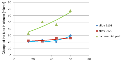

Fig. 5a:
Change in the tube wall thickness as a function of soaking time – Time of soaking [days] – Flux load 8 g/m2
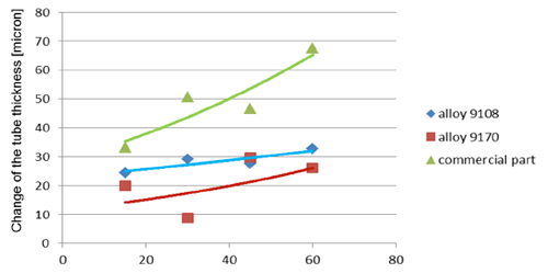
Fig. 5b: Change in the tube wall thickness as a function of soaking time – Time of soaking [days] – Flux load 16 g/m2

It seems that thinning of tubes at the beginning of the soaking test is quite rapid as compared to the period of soaking longer than 15 days.  In case of the NOCOLOK® ZnLi Flux, the maximum tube thinning is in the range of 30 microns.  The same maximum value for the commercial part is in the range of 65 microns.  There is no significant difference in the tube thinning between the two tested different alloys.

Industrial test

The industrial test was performed with condensers used for stationary application. However, they had a typical design as for automotive. In this case – since the standard production tube were not zinc coated – the testing was done using NOCOLOK® Li Flux.

Material of the tested part:
Fins: FA 6815 clad 4343 both sides
Tubes: HA9108
Manifolds: HA3905-R outside clad HA4045-D

Brazing was performed on industrial brazing line made of wet fluxer, dryer and Active Only (Seco/Warwick) brazing furnace.  Fluxing was done with NOCOLOK® Li Flux – concentration 13% for overhead spray and 43% for tube to manifolds joints.  The above concentrations were the same as for standard industrial production.  Also no changes were done in brazing parameters as compared to standard conditions.

Corrosion resistance of the brazed parts was checked by SWAAT (ASTM G85 A3).  In order to examine the parts after different times at SWAAT, a brazed part was segmented, and all the segments were tested in the same test chamber – but for different time periods.

Examination of the segments after 5 days in SWAAT did not reveal any significant progress of corrosion; however, after longer times, fin debonding was observed.  This examination did not show any differences between the parts fluxed with NOCOLOK® Li Flux and those fluxed with standard NOCOLOK® Flux.  More information was obtained when examining metallographic cross sections:
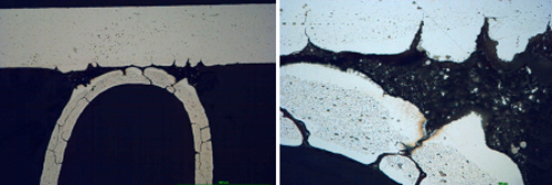

Fig. 6a: Structure of the samples brazed with NOCOLOK® Flux after 5 days in SWAAT 
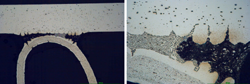
Fig. 6b: Structure of the samples brazed with NOCOLOK® Li Flux after 5 days in SWAAT

It can be observe that initially corrosion starts as intergranular attack on the fin material and as an intensive attack on the filler alloy. The filler is attacked selectively; firstly the alpha phase of the eutectic is removed.
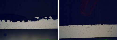

Fig. 7:
 Structure of samples brazed with NOCOLOK® Flux (left) and NOCOLOK® Li Flux (right) flux after 60 days in SWAAT

Already after 30 days of SWAAT, for both sample almost all the fins were detached from the tubes – thus the examination of the parts after 60 days of SWAAT was limited only to the tubes.

The surface of the tube in case of standard NOCOLOK® is corroded to a much higher degree than in the case of the part brazed with NOCOLOK® Li Flux.  The corrosion in both cases is initiated by intergranular attack; however later on it does not develop into pitting corrosion, but the removal of the tube material has laminar character.  It seems that NOCOLOK® Li Flux did not cause a change of the corrosion mechanism; it just delayed the corrosion processes.

The higher corrosion rate for samples brazed with standard NOCOLOK® Flux observed in the microscopic structures has been confirmed by measuring the tube wall thickness.  Results of those measurements (at least 10 measurements per point) are presented in fig. 8.  It should be worth noticing that the standard variation for the wall thickness measured after 60 days of SWAAT was 10.9µm for fluxing with NOCOLOK® Li Flux and 81.2µm for fluxing with standard NOCOLOK® Flux.  Such a large variation in the wall thickness in case of NOCOLOK® Flux would indicate that the “long life” capacity of the protection mechanism in this case was practically exhausted.
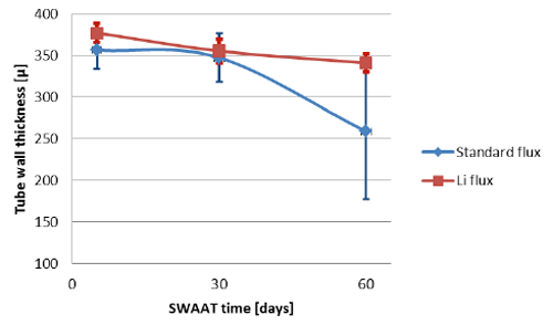

Fig. 8: Thinning of the tube wall during SWAAT

4 Conclusions

The experiment with the mock ups allowed for conclusions that there is no negative influence of NOCOLOK® Li Flux on the creation of Zn enriched sacrificial layer.  Presence of NOCOLOK® Li Flux in the mixture allowed for better protection of the sample parts against corrosion in stagnant water test.  One objective of stagnant water corrosion test is the simulation of stationary air conditioning unit humidity exposure.

It is possible to utilize in a flux mixture advantages of NOCOLOK® Zn and of NOCOLOK® Li.  Also as shown by testing with two different tube alloys, there is no significant difference in the tube thinning between different alloys.

Initial laboratory observations – that NOCOLOK® Li Flux improves resistance to corrosion in SWAAT condition – have been proven on industrial part.  Thus one option to increase the life time during SWAAT can be to use NOCOLOK® Li Flux.

Go to part 1

Literature

[1] A. Gray, H.W. Swidersky, L. Orman.
Reactive Zn Flux – an opportunity for controlled Zn diffusion and improved corrosion resistance.  AFC Holcroft 11thInternational Invitational Brazing Seminar, October 2006

[2] A. Gray, A. Afseth, H.W. Swidersky. The influence of residual flux level on the corrosion behavior of heat exchanger materials, ASST, May 2003

[3] Solvay Patent. WO10060869 A1 – Anti-Corrosive Flux – NOCOLOK®Li Flux, 2010

[4] Solvay Patent. WO11098120 A1 – Flux Forming an Insoluble Brazing Residue – Li Flux – Li3AlF6, 2011

[5] NOCOLOK®Li Flux New Brazing Flux with Improved Residue Performance

[6] NOCOLOK®Zn Flux – Technical Information

written by Leszek Orman, Radziszow / Poland; Hans-Walter Swidersky, Hannover / Germany

Abstract

In 2001 and in 2009 respectively, Solvay introduced two new fluxes for aluminium brazing: – NOCOLOK®Zn Flux (a ‘reactive flux’ – for the creation of precisely controlled sacrificial layers on part surfaces); and – NOCOLOK®Li Flux (for improving corrosion resistance of stationary air conditioning systems under stagnant water conditions).

When brazing with NOCOLOK®Li Flux, as validated on laboratory scale, some aluminium alloys show slightly better corrosion performance in SWAAT than parts brazed with standard flux.

On this basis, it was decided to investigate if a combination of NOCOLOK®Zn Flux and NOCOLOK®Li Flux can provide additional improvements in corrosion resistance.

Tubes of sample heat exchangers were coated with mixtures of Zn Flux and Li Flux – and brazed in an industrial furnace. Their corrosion resistance was checked by so-called soaking tests – i.e. by immersion in demineralized water over extended period of time.

In order to check the influence of NOCOLOK®Li Flux on corrosion resistance, some condensers were brazed under real industrial conditions, and their corrosion behavior was examined in SWAAT.

The results of this work indicate that a combination of NOCOLOK®Zn Flux and NOCOLOK®Li Flux can contribute to improved corrosion resistance at stagnant water conditions, and that NOCOLOK®Li Flux can delay corrosion attack in SWAAT.

1 Introduction

Corrosion resistance of heat exchangers exposed to different elements during service has been always one of the main concerns for the heat exchanger manufacturers and users. The most important methods for improving corrosion resistance of a given aluminium heat exchanger are:  selecting alloys for the exchanger parts in such a way that the galvanic potentials of the exchanger elements are properly balanced; creation of a sacrificial layer on a given part of the exchangers (usually tube surfaces); and coating the whole exchanger with a protective layer, which prevents a direct contact of the environment elements with the metal of the heat exchanger.

A common method for the creation of a sacrificial layer on the tube surface involves introducing Zn into the outer layer of the tube material.  Traditionally it is done by electro arc spraying of the extruded tubes with metallic Zn.  To improve the uniformity of the Zn enriched layer and to enable better control of the Zn diffusion profile, NOCOLOK®Zn Flux was developed [1].

With the flux on the aluminium parts to be brazed, a thin strongly adhering layer of post brazed flux residue remains on the surfaces after brazing.  Provided that this layer is uniform and covers all elements of the exchanger, it slightly improves corrosion resistance – acting as a barrier for element penetration [2]; however, for standard NOCOLOK®Flux this positive effect is not very strong.

Upon the introduction of all aluminium CAB produced condensers into stationary air conditioning systems, it was observed that the surfaces of such units – when exposed to stagnant water (for example from rain or condensation), can show signs of corrosion.  In response to that situation NOCOLOK® Li Flux was developed.  Reduced water solubility of NOCOLOK® Li Flux post braze flux residue has been attributed for slowing down corrosion rate of the brazed aluminium parts under stagnant water condition [3, 4].  Also it was observed that parts brazed with NOCOLOK® Li Flux (laboratory samples) show higher resistance to corrosion in SWAAT [5].  On this basis, it was decided to investigate whether a combination of NOCOLOK®Zn Flux and NOCOLOK®Li Flux can achieve further improvements of corrosion resistance, and if NOCOLOK®Li Flux can provide additional corrosion resistance for industrial parts in SWAAT.

2 Experimental

Determination of the flux mixture composition

In the first step of the experiment, brazing at industrial conditions of especially prepared mock-ups was performed (Fig.1). The primary task was to determine the correct proportion between the NOCOLOK® Zn Flux and Li cryolite (Li3AlF6). The mixture composition was established on an assumption that the lithium cryolite should react with K3AlF6(equation 2) in order to minimize the water solubility of the Post Braze Flux Residue [PBFR].  Thus the calculation was based on following reactions [1, 4]:

12 KZnF3 +  8 Al   →   12 Zn  +  6 KAlF4 +  2 K3AlF6                                (1)

Li3AlF6 +  2 K3AlF6   →   3 K2LiAlF6                                                           (2)

By adding the sides of equations 1 and 2 we obtain:

12 KZnF3 +  8 Al  +  Li3AlF6  →  12 Zn  +  6 KAlF4 +  3 K2LiAlF6             (3)

Substituting the atomic masses into equation 3, we obtain that the composition of the flux mixture should be:

NOCOLOK®Zn Flux – 91.7%; lithium cryolite – 8.3% by weight.  As stated in [6], a load in the range of 10 g/m2of Zn Flux (which corresponds to metallic level of Zn equal to 4g/m2) is sufficient for providing sacrificial layer on the substrate surface.  In order to envelope the above value for the current experiment 3g/m2and 6g/m2of metallic Zn load were chosen.  That corresponds to 8g/m2and 16g/m2of the NOCOLOK® Zn Flux + Lithium cryolite mixture.  Further on this mixture is called NOCOLOK®ZnLi Flux.


Fig. 1:  The assembled mock up with Data Pack thermocouples just before brazing

Materials used in experiment:

  • Flux: NOCOLOK® Zn Flux – 91.7% weight, lithium cryolite – 8.3% weight
  • Fins: HA 3968-K
  • Headers: HA 3905-R
  • Tubes, alloy 1: HA 9108
  • Tubes, alloy 2: HA 9170, both alloys coated on industrial machine (SAPA Precision Tubing) with NOCOLOK®ZnLi, load (8 and 16g/m2)

The fins, tubes and headers were manufactured by Hydro Aluminium Rolled Products.

Brazing of the mock ups was performed in industrial Active Only brazing line made by Seco/Warwick.  As measured by Data Pack®, the parts stayed at temperature over 580°C for about 5 minutes.

After brazing the Zn diffusion profile and resistance to the so called soaking test were evaluated.

3  Results and discussion

Mock up experiment

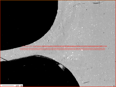
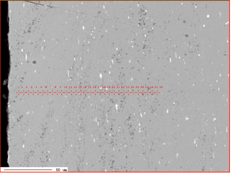
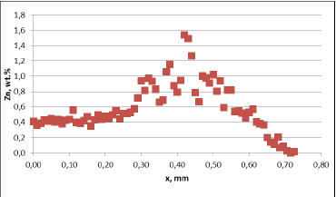
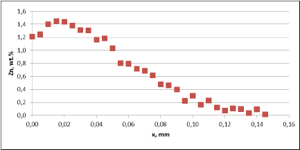
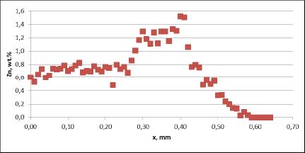
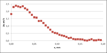
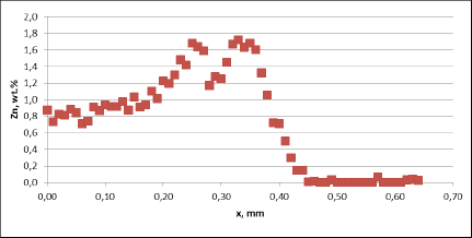
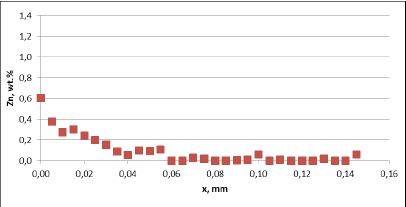
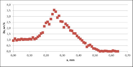
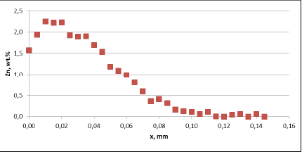
Zn diffusion profiles was measured by X-ray microprobe JXA 8230 made by JEOL. Applied accelerating voltage: 15kV with the beam current 30nA.  They were measured in two characteristic places: through the fin to tube joint and through the tube in the middle of the fin joints. This is shown in Fig. 2:


Fig. 2: Electron Back Scattered Image – example showing location of the analyses lines

Diffusion profile across the joint, Flux load 8g/m2, tube alloy HA9180
Fig. 3a:
  Zn diffusion profiles – as measured on the brazed mock ups, Diffusion profile across the joint, Flux load 8g/m2, tube alloy HA9180

Diffusion profile between the joints, Flux load 8g/m2, tube alloy HA9180
Fig. 3a:  Zn diffusion profiles – as measured on the brazed mock ups, Diffusion profile between the jointsFlux load 8g/m2, tube alloy HA9180

Diffusion profile across the joint, Flux load 16g/m2, tube alloy HA9170
Fig. 3a:  Zn diffusion profiles – as measured on the brazed mock ups, Diffusion profile across the jointsFlux load 16g/m2, tube alloy HA9170

Diffusion profile between the joints, Flux load 16g/m2, tube alloy HA9170
Fig. 3a: Zn diffusion profiles – as measured on the brazed mock ups, Diffusion profile between the jointsFlux load 16g/m2, tube alloy HA9170

Zn diffusion profiles – as measured on the commercial sample, Spot 1, Diffusion profile across the joint
Fig. 3b:
 Zn diffusion profiles – as measured on the commercial sample, Spot 1, Diffusion profile across the joint 

Zn diffusion profiles - as measured on the commercial sample, Spot 1, Diffusion profile between the joints
Fig. 3b: Zn diffusion profiles – as measured on the commercial sample, Spot 1, Diffusion profile between the joint 

Zn diffusion profiles – as measured on the commercial sample, Spot 2, Diffusion profile across the joint
Fig. 3b:
 Zn diffusion profiles – as measured on the commercial sample, Spot 2, Diffusion profile across the joint 

Zn diffusion profiles – as measured on the commercial sample, Spot 2, Diffusion profile between the joint
Fig. 3b:
 Zn diffusion profiles – as measured on the commercial sample, Spot 2, Diffusion profile between the joint 

For all mock up samples the depth of diffusion profiles is around 120 microns.  The maximum level of Zn concentration for lower flux load is at the range of 1.2% to 1.4% – and for higher flux load is in the range of 2.5%. These values seem to be typical for tubes coated with NOCOLOK®Zn Flux. Also the maximum content of Zn in the fillet seems to be rather well balanced with the Zn concentration on the tube surface (Fig. 3a).

For comparison, the diffusion profile of a commercial part was also investigated. In this case the diffusion profiles show quite significant differences – both in the depth of diffusion and the maximum Zn concentration on the tube surface. Also the Zn concentration is higher for fin to tube joint (Fig. 3b). This observation seems to be consistent with a well known fact that electric arc Zn coating is not uniform having places with high and low zinc load.

Go to part 2

Literature

[1] A. Gray, H.W. Swidersky, L. Orman.
Reactive Zn Flux – an opportunity for controlled Zn diffusion and improved corrosion resistance.  AFC Holcroft 11thInternational Invitational Brazing Seminar, October 2006

[2] A. Gray, A. Afseth, H.W. Swidersky. The influence of residual flux level on the corrosion behavior of heat exchanger materials, ASST, May 2003

[3] Solvay Patent. WO10060869 A1 – Anti-Corrosive Flux – NOCOLOK®Li Flux, 2010

[4] Solvay Patent. WO11098120 A1 – Flux Forming an Insoluble Brazing Residue – Li Flux – Li3AlF6, 2011

[5] NOCOLOK®Li Flux New Brazing Flux with Improved Residue Performance

[6] NOCOLOK®Zn Flux – Technical Information

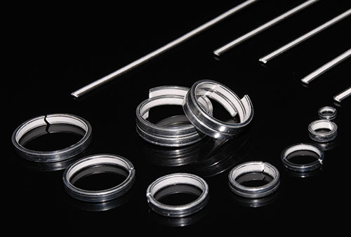
U‐shape brazing alloys with flux integrated into material

u-rings-picture

Advantages

  • Reduced labor cost
  • Reduced waste
  • No post-braze cleaning
  • Flexible design
  • Multiple applications
  • Ideal geometry for feeding
  • No hidden flux voids
  • Precise control of alloy and flux


Ideal for Preforms

  • Unlimited preform options
  • Flux flows unobstructed

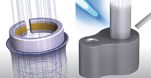
u-rings-drawing

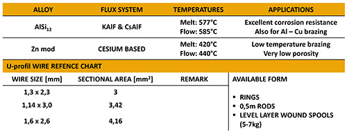
NON‐CORROSIVE FLUX

No post braze cleaning required, reducing the environmental impact associated with waste water

treatment

LESS CONTAMINATION

there are no powders leaching out to contaminate assembly equipment. The flux we deposit in the

channel stays in the channel.

Microsoft PowerPoint - HPa Flame brazing.pptx

Download the brochure.

To be continued…

Selecting the Correct Flux –WHAT?
The first requirement of an Aluminium brazing is to be chemically effective.
Fluxes are categorized as active (corrosive) and inert (noncorrosive).

Fluoride base fluxes → NON‐CORROSIVE
The fluxes leave the white gritty residue on the part. These fluxes include the higher temperature potassium
aluminium fluoride and the lower activated cesium aluminium fluoride Fluoride flux residues is tightly adhered to aluminium surface, relatively insoluble, not necessary to be removed. Fluoride flux operates by melting, spreading and dissolving of aluminium oxide layer.

Active fluxes ‐ Chloride base fluxes → CORROSIVE
The appearance of the part after brazing is bright and shiny. The chloride post braze residues must be removed by water washing or chemical treatment, to prevent the occurrence of electrolytic corrosion. These fluxes require a significant exposure to hot water to remove the corrosive flux residues. Attention must be given to the outside of the assembly and to any residues that have migrated to the inside of the part.
Chloride flux is reported to work penetrating aluminium oxides at weak points and breaking up the oxide/aluminium bond.

Selecting the Correct Flux –WHY?
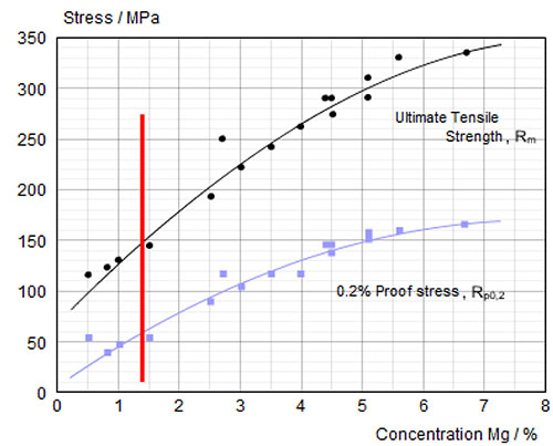
Effect of Mg content on mechanical properties and braze ability of Al‐alloys.

Microsoft PowerPoint - HPa Flame brazing.pptx

0,3‐0,6% Σ(Mg+Cu)% -> 2% cesium flux
0,6‐0,9% Σ(Mg+Cu)% -> 6‐10% cesium flux
0,9‐2% Σ(Mg+Cu)% -> 100% cesium flux
>2% Σ(Mg+Cu)% -> 726/0726 pastes

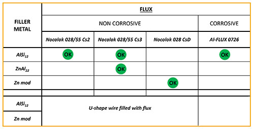
Correct filler metal / Correct flux
Fluxes must be thermally matched to the melting phase of the braze filler base metal.

Microsoft PowerPoint - HPa Flame brazing.pptx

CORROSIVE flux paste for the flame brazing of aluminium materials
Al‐FLUX 0726/2zG – Flux Paste
• As the active component of Corrosive‐Flux‐Paste, AL‐Flux 0726 contains a mixture of LiCl,
NaCl, KCl, inorganic‐ and complex‐ fluorides.
• Organic carrier systems are used to prepare a wide range of pastes for the flame brazing of
aluminium materials.
• Al‐Flux 0726 Flux Paste is typically applied by dispensing and brushing for flame brazing. No
component mixing is required. Products are supplied as ready to use products, requiring short
remixing

Download product information.

NON‐CORROSIVE Flux Paste for the flame brazing of aluminium materials
NOCOLOK® 028/55 Cs2 ‐ Flux Paste
NOCOLOK® 028/55 Cs3 ‐ Flux Paste
NOCOLOK® 028 CsD ‐ Flux Paste
From low‐temperature brazing (450°C) to the brazing of high‐strength aluminium alloys.

Download product information.

To be continued…

Case Study

A radiator core retrieved from service was examined for a suspected premature corrosion related failure.
Upon closer metallographic examination, no evidence of corrosion was found at the failed area.

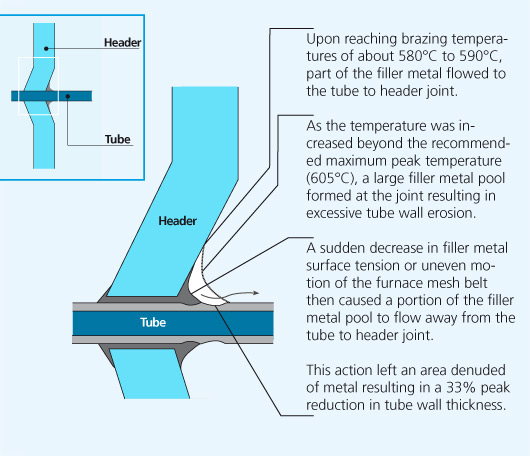
33% tube core erosion in the failure area


Header: AA4343/ AA3005

Tube: AA4343/ AA3003


It was concluded that the cause of the failure was in fact a mechanical failure occuring in the thinned wall area.

The following sequence of events proposes a rational explanation for the eroded tube area:

In service radiators are subject to internal pressure fluctuations and expansion and contraction due to heating and cooling. Mechanical failure was imminent and occured in the weakest part of the tube, the thinned down tube wall area adjacent to the tube to header joint.

Conclusions

Erosion of the base metal is undesirable since it reduces the wall thickness of the brazed component.
In addition Si penetration in the grain boundaries is known to increase the susceptibility to intergranular corrosion. Therefore proper filler metal management practices should be observed to prevent undesirable effects. One such factor easily controlled by the brazer is maximum peak brazing temperature.

Experimental

The effect of temperature on filler metal erosion was studied using an automotive radiator core.

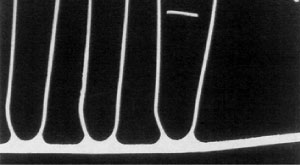
610 ° for 2 minutes

610 °C for 2 minutes - no thinning of the tube core

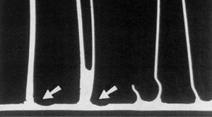
625 °C for 2 minutes

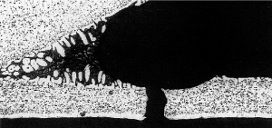
625 °C for 2 minutes - significant erosion of the tube core

In this case, joining progresses initially as expected. The cladding layer on the tube melts and flows by capillary action to the fin to tube joint and a normal fillet forms. However, as the peak brazing temperature is allowed to rise beyond the recommended maximum (605 °C) the following occurs:

  • The fluidity of the filler metal at the tube to header joint is increased and some of the liquid filler metal is released and flows to the nearest tube to fin joints.
  • Excess filler metal at the tube to fin joints accelerates dissolution of the tube core adjacent to the fin, eroding the tubewall thickness.
  • The excess filler metal pool is then drawn by capillary action in between the fins, particularly where the finspacing is narrow. The fins are drawn together by the strong capillary forces, displacing the fin from its original fin to tube position.
  • As the fins move together, drawing the filler metal pool from its original position, the denuded area is significantly reduced in cross sectional thickness.
Catastrophic Failures

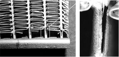
In some instances the extent of filler metal erosion is so severe that the entire thickness of the tube is consumed resulting in catastrophic failures.

More about this topic in our next issue.

Process related causes

The service life of a heat exchanger may be shortened due to corrosion caused by process related events. Some examples are listed below:

Excessively high brazing temperature or too long time at temperature will lead to excessive Si diffusion in the core. Si diffuses along grain boundaries and this can increase the susceptibility to intergranular corrosion. By maintaining proper time-temperature cycles and thereby minimizing Si diffusion, intergranular attack can also be minimized.

Copper in contact with aluminum will cause a corrosion related failure very quickly. Copper is noble (cathodic) to aluminum and when these two metals are in contact in the presence of an electrolyte, the aluminum will be consumed rapidly. This may occur in a heat exchanger manufacturing facility where both Al and Cu heat exchangers are produced and there is cross-contamination of process routes. It only takes one small Cu chip to land on the surface of Al during some part of the manufacturing process to cause a short-term failure in the Al heat exchanger. If both Al and Cu heat exchangers are to manufactured under the same roof, it is recommended (and practiced) to physically separate the two production routes with a wall and take extensive steps to avoid cross-contamination.

Carbonaceous residues can be generated on the heat exchanger surfaces during the heat cycle from residual lubricants, excessive use of surfactants, binders in flux or braze pastes etc. Carbon plays very much the same role as Cu in that it is noble to Al. In a corrosive environment, carbon residues act as a cathode and Al as an anode, leading to the galvanic corrosion of Al. The best preventative measure is to ensure that the heat exchangers are thoroughly and properly cleaned and degreased prior to brazing. This includes monitoring the flux slurry bath for any signs of organic contamination (for instance oil slicks).

Coatings

Painting a heat exchanger offers some level of corrosion protection, but is primarily used for cosmetic purposes. Painting will enhance corrosion protection if it covers the entire heat exchanger uniformly and is free from defects. In fact, paint defects or stone chips will accelerate corrosion locally. Many Al producers believe it is better to leave the heat exchanger unpainted to prolong its service life.

Conversion coatings such as chromate or phosphate conversion coatings work differently than painted surfaces. Conversion coatings enhance the natural oxide film on Al, essentially making it thicker and more resistant to hydrolysis. These types of coatings are most often used with automotive evaporators.