Schlagwortarchiv für: Electrostatic

flux-characteristics-and-transfer-systems-in-electrostatic-application


Attachment

Powder Fluidity Indicator

Definition of the Variables and Calculation of the Results

Preliminary remark:
The spraying factor Rm is a relative value for the evaluation of powders used for dry fluxing – especially when the material transport in the used equipment depends on the fluidization property of the powder.
Expansion factor:

Expansion factor [cm/cm] = Hfluid [cm] / H0 [cm]

For the calculation of the expansion factor, the mean values for Hfluid and H0 are used. The data for the mean values results from measurements of the powder height at 5 points.

Hfluid: powder height in fluidized condition
H0: powder height not fluidized and vibrator shut down
Hfluid = (Hfluid1+ Hfluid2+ Hfluid3+ Hfluid4+ Hfluid5) / 5
H0 = (H01 + H02 + H03+ H04+ H05) / 5

Powder flow (m) [g/ 0,5 min]
The mass (weight) of powder flowing out through the calibrated hole in 0.5 minutes calculated as median from 10 measurements.

Calculation of the median:

Median = m9+m2 / 2 for 10 single measures of m and m5< m3< m1< m7< m9< m2< m4< m8< m10< m6

Spray factor (Rm)

Rm [g/ 0.5 min] = m [g/0.5min]* expansion factor

The Spray factor results from the median of powder flow multiplied with the calculated expansion factor.

Go to Part 1

Go to Part 2

Go to Part 3

Go to Part 4

Go to Part 5

Go to Part 6

End of the article.

flux-characteristics-and-transfer-systems-in-electrostatic-application


Flux Transfer Systems in Electrostatic NOCOLOK® Flux Application

For these experiments, a fluxing booth from Nordson designed for semi-continuous production was used. This unit’s (216 cm height, 143 cm width, 270 cm depth) key components are a hopper, a spray gun, two filter cartridges and the necessary control units.
The work piece is placed on a grating, which can be manually moved back and forth. The spray gun automatically progresses from left to right and back in intervals of approximately 21 seconds (21 seconds for 65 cm; 3.1 cm/s).
Responding to recent market developments, a second flux transfer system was installed in this fluxer. An ITW/Gema hopper including spray gun and control unit were added to the booth.
The distance between the spray nozzles and the grating is 34 cm

Principles of Flux Transfer Systems in Electrostatic NOCOLOK® Flux Application

The Nordson hopper utilizes the principle of powder fluidization to convey the flux via a Venturi pump and a feed hose to the spray gun. An agitator in the hopper supports flux fluidization.
The ITW/Gema system has a hopper with a helix screw conveyor to mechanically transfer the powder into a funnel. From there, a Venturi pump transports the flux through a hose to the spray gun.
Both systems are equipped with vibrators in some positions to reduce flux buildup. The spray guns are operated with 100 kV to charge the powder.
The design of the Venturi pump and the electrical spray gun of the two systems are very different from each other. However, in view of the experiments described here, this was only of minor influence. The focus is on trends of flux behavior when samples with fine and coarse particle size distributions are compared. Using the technology type rather than the manufacturer’s name is even more in line with the objectives.

Experiments with Flux Transfer Systems:

Trials to determine the consistency of flux flow and deposition on radiators were performed, using sample 1 and sample 2 in the powder fluidization (Nordson) and the mechanical transfer (ITW/Gema) equipment.
As the first step, the control units (for flow air and/or helix speed) needed to be adjusted for each test to a flow rate that provided a flux loading of approximately 5 g/m². The experiment was then continued for 30 minutes without changing the equipment settings. In intervals of two to four minutes, radiators were placed on the grating for coating, and then weighed to determine flux loading. Each test series included ten or eleven units.
The results are summarized in the table ”Flux Deposition on a Heat Exchanger”. Material of sample 1 (”coarse” material) showed relatively consistent behavior in both systems. Variations are in a range of 0.7 g/m² with powder fluidization and 0.5 g/m² with mechanical transfer. For sample 2 (”fine” material), the findings indicate more significant fluctuation with powder fluidization. The range is 1.4 g/m². In the mechanical transfer system, the variations of sample 2 are lower, 0.5 g/m².
Due to the influence (and statistical variances) of the experimental conditions with different Venturi pump designs and different spray guns in both systems, the results only provide information on trends. As could be expected, the equipment relying on powder fluidization showed lower consistency with fine material. It is more difficult to fluidize fine material, and consequently it is more difficult to transfer flux powder by fluidization.
Sample 1, which has better fluidization properties, has lower fluctuations in both systems. This indicates a more beneficial performance of a flux powder with good fluidizing capabilities.

Mechanical Transfer System – Sample 1

6-1-mechanical-transfer-system-sample-1


Mechanical Transfer System – Sample 2

6-2-mechanical-transfer-system-sample-2


Table 3: Flux Deposition on a Heat Exchanger (30 Minutes Test)

6-3-flux-deposition-on-a-heat-exchange


Powder Fluidization System – Sample 1

6-4-powder-fluidization-system-sample-1


Powder Fluidization System – Sample 2

6-5-powder-fluidization-system-sample-2


These results were confirmed by other observations made during additional trials. Material with spray factors of approximately 45 g/0.5 min and higher (with good fluidization) flowed through the equipment pipes and hoses with less material buildup and created lower amounts of residue buildup on the spray nozzles. Large particles also partially compensate for the Faraday Effect, which makes it difficult for the electrostatically applied flux to penetrate the fin package (center of heat exchanger with tubes and fins).

Conclusions:

The experimental work for this paper identified and evaluated essential performance characteristics for electrostatic flux application:

  • Powder fluidization
  • Powder adhesion

The flux particle size distribution and the relative ratio of fine particles in the flux powder are key factors in dry fluxing.
A specific proportion of fine material in the flux is important for adequate adhesion.
Larger particles contribute to proper fluidization.
Equipment parameters for electrostatic fluxing must be adjusted to suit the specific flux properties.
Fluxes utilized for electrostatic application need improved fluidization characteristics, but not at the expense of adherence performance.

Go to Part 1

Go to Part 2

Go to Part 3

Go to Part 4

Go to Part 5

Go to Part 7

To be continued …

flux-characteristics-and-transfer-systems-in-electrostatic-application


Flux Powder Adhesion:

Dust formation and flux fall off are of general interest to the brazing industry. Regardless of the application method, dust generation (particularly airborne fines) must be avoided or kept to a minimum. If dust formation cannot be prevented, local exhaust ventilation and meticulous housekeeping are recommended.
The inhalation of flux dust in high concentrations over a long period of time constitutes a health hazard to exposed personnel. Due to the abrasion caused by flux dust, unprotected equipment surfaces of moving parts can show premature deterioration if not regularly maintained.
As mentioned above, flux adhesion in dry application is lower than in wet application. Forced convection heating zones are one possible area in the process where flux losses may occur. Other factors might be manual transfer of units or vibrations during mechanical transport. Some users improve adhesion by applying the powder on surfaces still lubricated with residual evaporative oils.
When excess flux dust is generated in the drying oven or the furnace, it can get into the exhaust steam and create difficulties with the exhaust treatment (i.e., quickly overload the filter or scrubber). If the exhaust is treated with thermal or catalytic processes (i.e., incineration of evaporative lubricants), separation of solid and gaseous components can become necessary.
Excess flux dust in the brazing furnace can also settle on the conveyor belt or on the furnace muffle. The conveyor belt can take this powder through the brazing zones, where it eventually melts. This may contribute to accelerated corrosion.

Users of dry fluxing technology are aware of the reduced flux adhesion. At most of the operations we were allowed to visit, dust formation due to flux fall off is kept to minimum levels by appropriate technical installations.

Experiments for Flux Powder Adhesion:

We researched the ability of flux powders to adhere to aluminum surfaces in electrostatic application. A very simple test was used to determine adhesion tendencies. This experimental arrangement is not simulating real production conditions. Nevertheless, it provides very useful information.
A plain square aluminum plate (0.5 m x 0.5 m) is electrostatically coated on one side with flux powder. The total flux weight is determined to calculate flux loading. The plate is then dropped (in vertical position) from 5 cm height to the ground and the flux loss is registered as percentage of original flux weight.
Attached is a diagram with the results for flux sample 1 and sample 2. For each material, ten measurements were performed. There is a certain variation of the individual figures; nevertheless, the trend is obvious. Sample 1 (”coarse” material) shows an average loss of approximately 33% compared to approximately 3% of sample 2 (”fine” material). This general tendency of powder with larger particle size distribution to adhere less than fine powder was also confirmed by additional experiments we made. The flux fall off in wet flux application under these test conditions is approximately 1%.

Dry Flux Application on an Aluminum Plate (0.25 m2) Flux Loss for a Fall from 5 cm Height

5-1-dry-flux-application


Flux powder is electrically charged in the gun. Usually, adhesion in electrostatic application is dependent on electrical forces. The flux loses the charge when it hits the grounded heat exchanger. Gravitational forces are now competing with relatively weak Van-der-Waals forces. This explains why fine particles adhere better.
Large flux grains are affected more by gravity, and consequently fall off more easily. We were able to synthesize a flux with very large average particle size distribution which fluidized perfectly (spray factor 143 g/0.5 min; i.e., twice as ”good” as sample 1). However, when this material was used for electrostatic application, the air flow from the spray gun blew away a lot the flux just deposited on the surface.

Go to Part 1

Go to Part 2

Go to Part 3

Go to Part 4

Go to Part 6

Go to Part 7

To be continued …

flux-characteristics-and-transfer-systems-in-electrostatic-application


Experiments for Flux Powder Fluidization:

To illustrate the relationship between flux properties and fluidization, a series of tests was carried out using Sample 1 and Sample 2. Attached are print-outs of the particle size distribution analysis (Sympatec Helios H0851; dry powder analysis with laser) of both materials.

Table 1: Particle Size Distribution

4-1-particle-size-distribution

Sample 1 shows coarser grain structure than sample 2. There are considerably more fine particles in sample 2, and most of that material has a size of below 5 μm. The spray factor of sample 1 (”coarse” material) is 71.88 g/0.5 min. This correlates with very good fluidization properties which was confirmed during tests in the electrostatic spray booth (see below).

Sample 1

4-2-sample-1-particle-size


4-3-sample-1-volume-destribution


For sample 2 (”fine” material), a spraying factor of 7.35 g/0.5 min was found. This reflects extremely poor fluidization properties, also confirmed by tests in the spray booth. The above indicates that there are at least three material characteristics connected to particle size affecting fluidization:

  • Average particle size
  • Quantity of fine particles
  • Maximum particle size

Sample 2

4-4-sample-2-particle-size


4-5-sample-2-volume-destribution


To further identify the effect of these factors, we tested mixtures of the two samples. In increments of 10%, sample 1 and sample 2 were blended. Then the spray factors of the mixtures were determined.

Table 2: Spray Factors in [g/0.5 min] of Sample Mixtures

4-6-spray-factors


As illustrated in the graph (see attachment), the relationship of spray factor and sample mixture ratio is not linear. Instead, it shows a rapid decline once the content of fine material is approximately 20 to 30%. We were able to specify the spray factor range of successfully performing flux powder to approximately 45 g/0.5 min in experiments with our dry fluxing booth, and from situations reported by our customers.

Spray Factor for Sample Mixtures

4-7-spray-factor-for-sample-mixtures


The ability of a powder to fluidize is very important for its performance in electrostatic application. However, it is not the only factor.

Go to Part 1

Go to Part 2

Go to Part 3

Go to Part 5

Go to Part 6

Go to Part 7

To be continued …

flux-characteristics-and-transfer-systems-in-electrostatic-application


Flux Powder Fluidization:

In an effort to develop a flux with more desirable properties for electrostatic application, the first step is to qualify criteria. In summary of the above, it is apparent that fluidization is one of them. There is standard equipment available on the market to quantify fluidization characteristics. However, when we tested these fluidity indicators, we found the fluidization ability of flux powder to be so poor that the results were meaningless unless a vibration unit was attached to the equipment. A photo of the modified installation can be found in the attachments. We combined a Binks-Sames powder fluidity indicator (AS 100 – 451 195) with a Fritsch vibration unit (L-24). The equipment consists of a fluidizing cylinder with a porous membrane on the bottom. The cylinder is mounted to a vibrator with a fixation plate. After the sample material (250 g) is placed in the cylinder, the vibration is turned on (via the vibrator control unit) and a consistent flow of dry nitrogen (via the fluidity meter control unit) is forced through the porous membrane. Depending on its potential to fluidize, the powder will start to expand until an equilibrium is reached (one minute). Measurements of the original and the fluidized height are taken at different points (see attachment).

3-1-fluidmeter-vibrator-control-unit

Powder Fluidity Indicator

3-2-indication-of-the-locations-for-the-measure-of-the-height-of-the-powder

Indication of the locations for
the measure of the height of the
powder in both fluidized and
non fluidized condition.

3-3-collecting-powder-as-it-comes-out-of-the-calibrated-hole

Collecting powder as it comes out of the
calibrated hole.

The second parameter determined with this device is the weight of powder flowing through a small hole on the side of the cylinder (as can be seen on the picture). Similar to the above procedure, the sample is fluidized in the cylinder. The side hole is then opened for 30 seconds, and the powder flowing out is caught in a beaker and weigh.

The spray factor is a combination of the expansion factor and the powder flow. Especially in dry flux application, where the material transport depends on fluidizing properties, the spray factor presents an important relative figure for powder evaluation.

Go to Part 1

Go to Part 2

Go to Part 4

Go to Part 5

Go to Part 6

Go to Part 7

To be continued …

flux-characteristics-and-transfer-systems-in-electrostatic-application


The background of electrostatic flux application:

When controlled atmosphere brazing with non-corrosive fluxes was introduced, the only realistic method for using the flux was wet application. This strategy was supported by the physical and chemical properties of flux powder.

Non-corrosive fluxes for aluminum brazing consist of potassium fluoroaluminates (inorganic fluorides) with low water solubility. The majority of the flux products on the market are manufactured by precipitation in aqueous solution. These show a rather fine particle size distribution, i.e. from one to fifteen micrometers (1 – 15 µm) for most of the grains (50% and more) and reaching from 0.5 – 50 µm with an average particle size between four and ten micrometers (4 – 10 µm). This type of powder is ideal for slurry application, as the fine particles prevent the flux from settling too fast. Also, when sprayed on a clean surface under wettable conditions, they present a uniform, very thin and fully adhesive coating after drying. As mentioned earlier, the flux slurry needs to be agitated continuously and the concentration must be monitored in order to guarantee consistent flux loading (i.e., flux weight per surface area).

The most significant problem in wet application is waste water. With stricter requirements and limitations for trace impurities in waste water, the pressure to reduce water consumption increases. At the same time, production capacity is expanding worldwide. Waste water treatment is expensive, and some brazing operations have limited experience in this field. In addition, more and more facilities are constructed in areas where water appropriately treated for flux slurry preparation is scarce and costly.

The challenges of electrostatic flux application:

Electrostatic powder coating has been standard technology for many years, and it was only a question of time before it was also realized in flux application. The following will focus on essential flux properties and basic equipment arrangements.

Some material characteristics of non-corrosive brazing fluxes make it difficult simply to transfer the normal powder coating equipment to the fluxing area and use it there. Most powders utilized for electrostatic application are either designed with special properties or already contain them. Important elements are:

  • Particle shape and particle size distribution
  • Ability to accept and to hold electrical charge

Particle size distribution has a significant influence on the ability of a powder to fluidize and to flow. Better fluidization characteristics lead to better equipment performance. Consistent flux transfer and the ability to flow through pipes and plastic hoses is directly affected by fluidization. Additionally, it has been observed that good fluidizing material shows less tendency to build up in the equipment. Buildup can quickly result in interruptions of the flux flow. When this buildup is expelled the nozzle may release an excessive amount of flux. This excess will in turn be deposited on the surface of the part, resulting in non-uniform flux distribution. It is possible to induce charge on flux when it travels through an electrical field. However, the powder, by its chemical and physical nature, displays instantaneous charge decay when it hits the grounded heat exchanger. Therefore, the forces that adhere the flux to the part are not electrostatic forces, but are more likely Van der Waals forces. In dry flux application, the following complications have been described by users when operating conventional flux qualities:

  • Fluidizing the powder and material transport is difficult. Vibration or stirring is necessary to improve on these characteristics
  • Problems with consistency of flux flow and uniformity of applied flux
  • Adhesion of deposited flux is inferior when compared with wet application
  • High humidity causes physical adsorption of water molecules to the fine powder dust in the booth. This may result in agglomerations
  • Recovering, recycling and reusing flux requires special attention

Go to Part 1

Go to Part 3

Go to Part 4

Go to Part 5

Go to Part 6

Go to Part 7

To be continued …

flux-characteristics-and-transfer-systems-in-electrostatic-application


Introduction:

This article summarizes some experimental results of a project on electrostatic application of non-corrosive fluxes for aluminum brazing. The objective is to qualify and quantify flux powder properties and equipment parameters with positive effect for dry flux technology.

For more than 30 years, controlled atmosphere brazing (CAB) [NOCOLOK ® Flux brazing] has been the leading technology for the manufacture of aluminum heat exchangers for the automotive industry.

The most common flux application method is by spraying an aqueous suspension. Constantly agitated flux slurries with concentrations of approximately 10 – 35% solids are pumped from tanks to fluxing booths. All aluminum surfaces involved in the brazing process are coated with the slurry, resulting in a uniform flux layer. Excess flux slurry is removed with a high-volume air blow; the excess is then collected, recycled and reused in the fluxing booth. Before going into the furnace, the heat exchangers are pre-dried in a separate drying oven to remove residual moisture.

In wet flux application, the following are critical factors and need specific observation by the user:

  • Flux slurry concentration
  • Consistency and uniformity of applied flux
  • Flux loading on heat exchangers
  • Drying step

Depending on the particular brazing operation, flux slurries may become contaminated with dust, metal particles, rust and organic compounds. The used slurry also contains the soluble portion of the flux (i.e., small levels of potassium, fluoride and aluminum), and must therefore be treated and then disposed of in accordance with environmental regulations.

Over the past five years, some users of NOCOLOK brazing technology have implemented dry flux application methods. Based on the principles of powder paint technology, an alternative application technique was introduced in the brazing industry.

The benefits of electrostatic application are directly related to the problems of wet application:

  • No need to mix slurries
  • No need to monitor slurry concentration
  • No need for a surface wettability concept (i.e., surface treatment or wetting agent)
  • No separate drying step required to remove moisture
  • No waste water effluent

Particularly when dry fluxing is used in connection with evaporative oils and lubricants, the objective is to eliminate or significantly reduce water consumption during the process.

Go to Part 2

Go to Part 3

Go to Part 4

Go to Part 5

Go to Part 6

Go to Part 7

To be continued …

Additional information to the Article Flux Application: Electrostatic Fluxing

In dry flux application, the flux powder is electrostatically charged (typical voltage is ~ 100 kV) and applied to a grounded work piece. An electrical field results in flux deposition of the work piece. In practice, anisotropic distribution of the electric field can influence the homogeneity of powder coverage. At edges powder may accumulate, while penetration of powder into deep/thick fin packages (e.g., in case of double row tubes) can be limited by the Faraday cage effect.

Flux powder is electrically charged in the gun. However, it loses charge relatively fast when it hits the grounded heat exchanger. Therefore adhesion of the flux on the work piece is established rather by relatively weak Van der Waals forces than by electrostatic forces. Fine flux particles adhere better on the surface – but they are more difficult to operate with in the dry powder feeding system.

The relatively fine flux particles are more difficult to handle in dry powder feed systems compared to coarser paint powders – therefore the equipment used for electrostatic flux application is adapted to meet the specific requirements. Venturi pump, hose diameter, air flow and spray nozzle suitable for flux application are designed to minimize the possibility for powder buildup and clogging in the system. Powder transport within the hose system and the spray nozzle is further enhanced by introduction of additional air streams. The direction of the powder flow should always be from top to bottom. Sharp changes in flow direction must be avoided. In critical areas additional vibration units are installed to avoid powder buildup.

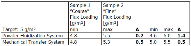
There are two types of powder feed systems established on the market (see the illustrations in the article):

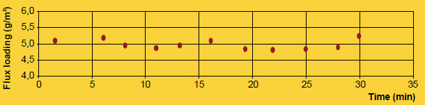
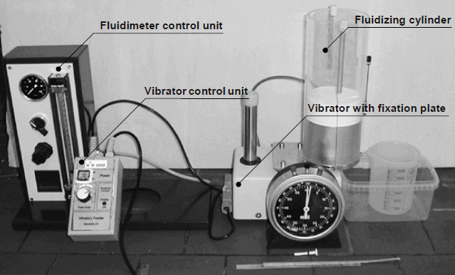
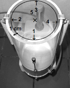
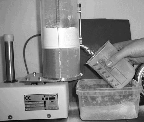
The first type starts with the flux powder being fluidized in a fluidization vessel by compressed air that is fed through a porous membrane at the bottom of the fluidization vessel. The air going through the flux makes it behave like a fluid, since the powder is essentially diluted with air. A pick up tube attached to a Venturi pump is extended into the fluidized flux. Powder dosage is controlled by the volume of air flow through the pump. To optimize fluidization the vessel may additionally be equipped with a stirrer.

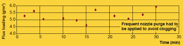
This type of feed system works perfectly well for classic electrostatic paints powders that are easy to fluidize, however, it may be difficult to establish a stable fluidization with ’standard‘ flux powder (i.e. the flux powder quality offered for wet/slurry-based flux application).

Fluctuations in density of the fluidized bed can result in inhomogeneous spray pattern (splashing) and might be a source for flux buildup within the system.

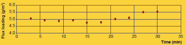
NOCOLOK® Flux Drystatic is optimized to minimize the challenges of powder feeding, while providing sufficient fine particle fraction for good adhesion properties.

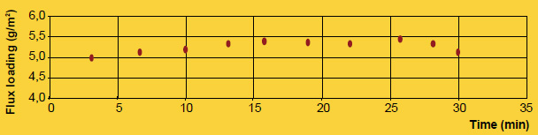
The second type of powder feed system works on the principle of feeding the powder by a rotating helix screw (see the illustrations in the article above). Because of the mechanical displacement of the flux powder from the hopper, such devices minimize fluctuations of flux powder flow.

Most mechanical type of dry flux feed systems work with standard quality NOCOLOK® Flux as well as with special ‚Drystatic‘ grade NOCOLOK® powder.

To achieve flux distribution patterns for specific process needs (e.g., higher flux loads in tube to header areas, coating from both sides of thick cores), multiple spray nozzles are arranged for deposition of the necessary flux load at different locations of the heat exchanger.

Dry fluxing booths must be equipped with a filter system to collect the overspray. The overspray material is recycled within the booth. To avoid accumulation of impurities within the recovered flux, it is necessary to take care of the booth environment (i.e. avoid dust, fumes, and high humidity level) as well as for the quality of the compressed air used. Contamination introduced by the heat exchangers or the transport belt must be prevented as well.

Due to the relatively weak flux adhesion (compared with wet- or paint- application methods), handling of dry fluxed parts should be done with special care to avoid flux fall off, especially at higher flux loads. To reduce flux fall off, some users perform electrostatic fluxing on heat exchangers with evaporative oils still present on the surfaces. Thermal degreasing in this case takes place after fluxing – just before the parts enter the brazing furnace.

This technique, also known as dry fluxing is gaining popularity as an alternative fluxing practice and therefore will be described here in some detail. Dry fluxing is a technology whereby the flux is electrostatically charged and applied to a grounded work piece, in our case a heat exchanger or individual heat exchanger components. The electrostatic attraction causes a layer of flux to be deposited on the work piece. A typical flux application system consists of a powder feed system, the electrostatic spray gun, the gun control unit, the grounded work piece and finally the flux recovery system.

The advantages of such a system over conventional wet fluxing are evident. Since the flux is applied dry, there is no need to prepare flux slurries, hence no need to monitor flux slurry concentrations. There is also no wastewater generated therefore more environmentally friendly. The dehydration or dry-off section of the furnace may be eliminated since the heat exchangers enter the furnace already dry. However, one must keep in mind that this is a relatively new fluxing technique and there are some minor drawbacks. Flux adhesion is not as good compared to that of wet fluxing. The flux also tends to accumulate on the leading edges of the heat exchanger and because of the Faraday cage effect, may have some difficulties in coating into corners or more specifically, in tube to header joints.

Powder Feed Systems
Presently, there are two types of powder feed systems on the market. The first type begins with the flux being fluidized in a hopper. Dry compressed air is fed through a porous membrane in the bottom of the hopper. The air rising through the volume of flux makes it behave like a fluid since the powder is essentially diluted with air. A pick up tube attached to an air pump is extended in the fluidized flux. Powder flow is then regulated by controlling the air-flow to the pump which is then delivered through the feed system to the spray gun. This type of feed system works perfectly well for powder paints. However, the flux has very different physical characteristics than powder paints (particle size, morphology) and so is difficult to fluidize. This must be taken into consideration when the manufacturer designs a powder feed system that relies on fluidization.

Dry Fluxing – Mechanical Flux Transport

The second type of powder feed system works on the principle of mechanical delivery or positive displacement. This means that the powder feed rate to the air pump is controlled by a screw or auger. The flux is contained in a main feed hopper and delivered mechanically at a controlled feed rate to the air pump. Powder flow is thus regulated by controlling the auger feed rate. This powder feed system does not rely on the flux being fluidized. Nonetheless, modifications over conventional mechanical powder feed systems are still necessary to overcome the differences between the flux characteristics and conventional powder paints.

Dry Fluxing – Powder Fluidization

Japanese heat exchanger manufacturers have used the technique of dry fluxing for many years now. Within the last few years, North American and European manufacturers have also installed electrostatic fluxing stations. Experience with this technique is being accumulated at a rapid rate, given that the equipment manufacturers and flux suppliers are taking an active role in improving the technology.