The NOCOLOK International Brazing Seminar will provide information concerning the manufacturing practices commonly used for brazing operations and, in particular, will address the three fundamental aspects of the industrial-scale brazing of aluminium.
Schlagwortarchiv für: CAB
During recent years, gel blockage in engine coolant systems with aluminum heat exchangers produced by CAB has gotten more and more attention in the automotive industry. A general understanding of gel formation processes in engine coolants and the role that flux residues on internal surfaces of brazed heat exchangers may or may not have is of significant interest.
The pandemic situation these days forces us to do things in a different way and to be more innovative. Therefore, the 20th annual technical training event was organized as a Google Meet Webinar – on 2 days tailored for NAM and Asia time zones beginning of November 2020.
On October 8th & 9th, 2019 – for the 18th time since 2001 – the Aluminium Brazing Seminar took place at Solvay Fluor in Hanover (Germany). There was a ‘full house’ with 31 participants from 12 countries – representing 15 companies – plus 5 Solvay participants joining this technical training.
What is NOCOLOK® Cs Flux (SM)? (Synthesized Material)
NOCOLOK® Cs Flux is used for brazing of aluminium alloys with higher magnesium levels. The Cs flux currently available for CAB (Controlled Atmosphere Brazing – furnace brazing) is a technical mixture (i.e. a mechanical blend) of K-Al-F flux (NOCOLOK® Flux) with Cs-Al-F flux – this product is offered under the name NOCOLOK® Cs Flux (TM): Technical Mixture.
The new NOCOLOK® Cs Flux (SM) is a fully synthesized material – i.e. a unique and homogenous product. The Cs is completely embedded in a Cs-K-Al-F matrix during the manufacturing process.
Advantages
When comparing the characteristics and application of blended Cs Flux „(TM)“ with synthesized material „(SM)“, there are notable advantages of the new quality:
- The mixture can show settling and separation in flux slurries and paints. This is caused by differences in the density, the particle size, and the solubility of the two compounds in the blend.
- In the new fully synthesized material – with the Cs completely incorporated in a Cs-K-Al-F matrix – the density is consistent and the particle size more uniform. We have a homogeneous powder with improved stability in suspensions (i.e. for slurries, paints, and pastes).
- In addition, the overall solubility is reduced when compared with the blended material.
- There will be less settling and less separation – which means that there is enhanced application performance with NOCOLOK® Cs Flux (SM).
NOCOLOK® Cs Flux (SM) is on stock at our Wimpfen facility and available right away.
Worldwide Registration
For a number of years, more and more countries are converting their existing chemical regulations or are implementing new regulations. In many cases, these regulations can be considered as an adaption of the European REACH Regulation. A registration of chemical substances or reaction masses is required, including comprehensive material data sets and risk assessment.
Solvay appreciates and supports these new product safety initiatives.
As a consequence, however, this leads to that in order to fulfill all regulatory requirements new products can only be introduced stepwise to other countries.
NOCOLOK® Cs Flux (SM) has already been successfully registered according to the European REACH Regulation and can be used without restriction within the European Union. Please also refer to our Safety Data Sheet, which is available on request. Registration for other countries/regions will be done successive. For more information, please contact our local sales offices.
Flux-Green-Filler-Stop (GFS) “stops” molten brazing filler metal from flowing into areas where it is unwanted, thus the surfaces remain clean and free from the presence of any filler metal.
Brazing filler metals do not like to bond with, or flow over, any dirt, grease, or oxides so the presence of any of such contaminants can prevent the filler metal from flowing over the surfaces of those parts to be brazed where these contaminants are located.
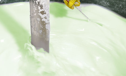
Therefore, GFS compounds are very effective at preventing molten filler metal flowing into protected areas. The GFS compounds are mixed with a liquid carrier solution and can be applied onto metal surfaces by using a small brush or by spraying or dipping.
For more information, please download the new brochure.
Brazing aluminum products such as radiators, condensers, evaporators, etc. for the auto industry is a mass production process. The brazing operation is generally carried out in a mesh belt furnace under a nitrogen atmosphere and is commonly known as ‘CAB’ – Controlled Atmosphere Brazing.
Accurate temperature measurement of the product throughout the furnace can be critical. Using a ‘through furnace’ temperature profiling system to measure product temperature is common practice within the industry, and the benefits are well established. There are also some known disadvantages to using these types of systems and here we look at recent developments to overcome these problems.
The ‘through furnace’ profiling system measures temperature by connecting thermocouples at specific points on the product which feed temperature information back to the data logger. The data logger is protected from the heat of the furnace by a ‘hot box’ or thermal barrier, allowing the system to travel through the furnace together with the product, storing valuable temperature data which is analysed at the end of the process using specialized software.
As previously stated the benefits of using temperature profiling systems are well known, however there are some disadvantages, these are:
- The thermal barrier normally has a very limited life span as parts of the insulation package are subject to acid attack from chemicals within the flux.
- Oxygen can leak from within the thermal barrier while it is in the furnace, potentially contaminating the nitrogen atmosphere.
A. Acid attack
During the braze cycle, moisture in the air inside the ‘hot box’ or thermal barrier will combine with chemicals in the brazing flux to form hydrofluoric acid which attacks the high temperature cloth covering the microporous insulation. Once this cloth begins to break down, the unprotected insulation at the entrance to the ‘hot box’ wears away increasing the aperture where the thermocouples enter. This allows heat in, potentially damaging the data logger, and lets oxygen escape into the furnace atmosphere, which may affect braze quality.
The life of this type of thermal barrier is severely reduced leading to high maintenance costs. The solution uses a robust ‘drawer’ design rather than the traditional ‘clam shell’ type.
This eliminates exposure of the high temperature cloth to the aggressive flux atmosphere, and significantly increases the life of the barrier. This new type of thermal barrier has been used in daily production since April 2011 at many leading automotive parts suppliers, with one major North American auto manufacturer reporting over two thousand uses without any wear problems.
B. Oxygen leakage
Whether the thermal barrier is a ‘clam shell’ or ‘drawer’ type it will contain air. As the system travels through the furnace the air begins to warm up and expands. As it expands it begins to leak out into the furnace atmosphere, which may be an issue to some users.
There are two areas within the thermal barrier where air will accumulate – within the microporous insulation, and in the spaces around the data logger and heat sink. A ‘two stage’ approach has been developed to remove this air.
Firstly eliminating the air deep within the microporous insulation is achieved by heating the whole thermal barrier or ‘hot box’ in a high vacuum, then back filling with nitrogen. This operation is carried out as the last stage in the manufacturing process.
Secondly, as an option for users with sensitive processes, all remaining air in the spaces around the data logger can be purged with low pressure nitrogen just prior to placing the system in the brazing furnace.
The nozzle for the nitrogen purge has been designed to allow free flow of the gas through the barrier, but by use of strategically placed internal ‘baffles’, heat penetration is minimized during the brazing process.
Conclusion
Although using a profiling system to monitor the product temperature in a CAB furnace has generally been considered high maintenance, it was judged that the value of the data obtained was worth the extra cost. However through careful system design a solution has been engineered that successfully overcomes these problems, saving maintenance costs and allowing the ‘hot box’ temperature profiling system to be used on a more regular basis.
Dave Plester, Director
Phoenix Temperature Measurement
www.phoenixtm.com
sales@phoenixtm.com
Approach to non-corrosive fluxes for further reduced residue solubility and improved magnesium tolerance
Technical Information by Ulrich Seseke-Koyro, Hans-Walter Swidersky, Leszek Orman, Andreas Becker, Alfred Ottmann
We split the article in four parts:
- Abstract and Basic Experimental Laboratory Procedures
- Reduced Flux Residue Solubility
- Improved Magnesium Tolerance
- Summary and Outlook
Summary
Our research activities so far have been focusing on flux blends with additives to validate lower water solubility of post braze flux residue. Another objective of this work was to allow for brazing of Al alloys with increased Mg levels using non corrosive fluxes.
First steps have been made with selected flux blends. This paper reflects the current project status, but more work still needs to be done for further improvement.
Low flux residue solubility
It has been shown that the flux residue water solubility is reduced by combining KAlF4 with AEFs (“KAlF4 compound concept”); among them BaF2 being the most promising candidate.
Fluxes for higher Mg tolerance
Flux blends containing KAlF4 plus CsAlF4 and Li3AlF6 seem to be a promising approach to improve brazing of higher Mg containing aluminium alloys.
Aluminium coupons samples (AMAG 6951 with 0.68% Mg) for the base coupon and the angle (1.36% Mg in the joint interface) require flux loads as high as 15g/m2 for successful brazing.
Good joint formation can be achieved at 5g/m2 load on samples with 0.68% Mg content. Thus brazing of higher Mg level Al-alloys with appropriate flux mixtures at process-typical loads seems to be feasible.
Outlook
For the continuation of this project, we need to define the Mg range for real industrial aluminium heat exchanger needs. We think that this can best be done in a joint effort of HX manufacturer, Al material supplier and flux producer.
- P Garcia et al, Solubility Characteristics of Potassium Fluoroaluminate Flux and Residues, 2nd Int. Alum. Congress HVAC&R, Dusseldorf (2011)
- P Garcia et al., Solubility and Hydrolysis of Fluoroaluminates in Post-Braze Flux Residue, 13th AFC Holcroft Invitational Aluminum Brazing Seminar, Novi (2008)
- J Garcia et al, Brazeability of Aluminium Alloys Containing Magnesium by CAB Process Using Cs Flux, VTMS5, 2001-01-1763 (2001)
- H Johannson et al, Controlled Atmosphere Brazing of Heat Treatable Alloys With Cesium Flux, VTMS6 C599/03/2003 (2003)
- Handbook of Chemistry and Physics; Ref. BaSO4: 0.0025 g/l
- U Seseke, Structure and Effect – Mechanism of Flux Containing Cesium, 2nd Int. Alum. Brazing Con., Düsseldorf (2002)
Approach to non-corrosive fluxes for further reduced residue solubility and improved magnesium tolerance
Technical Information by Ulrich Seseke-Koyro, Hans-Walter Swidersky, Leszek Orman, Andreas Becker, Alfred Ottmann
We split the article in four parts:
- Abstract and Basic Experimental Laboratory Procedures
- Reduced Flux Residue Solubility
- Improved Magnesium Tolerance
- Summary and Outlook
Improved Magnesium tolerance
Mg additions to Al alloys contribute to higher strength properties. The ongoing trend in saving weight by down-gauging of Al sheet thickness requires sufficient mechanical stability. One option for the production of higher strength Al alloys is to increase the Mg content.
A disadvantage of Mg is the interaction with potas-sium fluoroamuminate fluxes during brazing, which results in poor joint formation [3] [4]. This effect, known as “flux poisoning”, is caused by the formation of high melting compounds. The addition of caesium and other metals to the flux helps to compensate to a certain degree the poisoning [6].
For the first set of laboratory brazing experiments we chose commercially available AMAG 6951 brazing sheet (0.68% Mg, 4343 clad) and clad-less AMAG angle material (0.68% Mg) to investigate the brazing performance and joint formation. In this situation the metal-to-metal interface adds up to 1.36% Mg (2 x 0.68%) in total.
Table 1 shows a list of representative flux combina-tions with NOCOLOK® types, KAlF4, Li3AlF6. CsAlF4, and AEFs.
We repeated all brazing tests with each sample three times.
Flux Type | Load | Fillet visual validation | Comment |
---|---|---|---|
NOCOLOK® Cs Flux | 10 g/m2 | 100% | very small joint inconsistent seam |
MD001212 LiCs24 | 10 g/m2 | 100% | small joint weak seam |
MD001223 LiCs43 | 10 g/m2 | 86% | small joint inconsistent seam |
AB039215 KAlF4/BaF2 | 10 g/m2 | 52% | small joint inconsistent seam |
NOCOLOK® Cs Flux | 15 g/m2 | 100% | weak seam |
MD001212 LiCs24 | 15 g/m2 | 100% | thicker than with NOC Cs Flux |
MD001223 LiCs43 | 15 g/m2 | 100% | thicker than with NOC Cs Flux |
AB039215 KAlF4/BaF2 | 15 g/m2 | 98% | weak seam slighly better than NOC Cs Flux |
Table 1: Brazing trials: AMAG clad – AMAG clad-free angle different flux blends based on KAlF4 plus BaF2/Li3AlF6/CsAlF4
The angles from most of the AMAG specimens could be removed after brazing by pulling. Only a broken inner and outer fractured seam line was left – as can be seen below in picture 1 a.
Picture 1: a) Photos, b) and c) SEM/EDX of NOCOLK® Cs Flux brazed sample (load 15 g/m²) Coupon 0.68% Mg, angle 0.68% Mg – angle removed by pulling
From the SEM analysis it is evident that a proper met-allurgical joint between base and angle has not been formed.
Picture 2: SEM/EDX analysis of aluminium ‘angle on coupon‘ brazed with KAlF4/BaF2 blend
There is flux residue present in the pulled apart fillet. This indicates that the liquid filler alloy was not capa-ble of pushing out completely the flux of the joint and it could be an explanation for the weakness of the fillet.
However, in case of the blend MD001212 LiCs24 with load 15g/m2 the joint structure is thorough as can be seen in picture 3 a).
Picture 3: Microstructures of the brazed joints
a) Flux MD001212, load 15g/m2
b) Flux MD001223, load 15g/m2
It is worth mentioning when connecting blocks are brazed to condenser manifolds often a high load of manually applied flux is used in order to overcome the high Mg content in the block material. For such a case using the mixture MD001212 would allow for having quite high Mg content in the block material, which can be required by the designers of condens-ers.
The total concentration of 1.36% Mg (joint interface) is probably too high, because for most brazing applica-tions, a flux load of 15g/m2 is impractical. Thus, we decided to reduce the level of Mg in our samples to half – i.e. to 0.68% – by switching to an AA1050 (Al 99.5%) angle. We also reduced the flux load to a more process-typical level of 5g/m². The results are listed in table 2:
Flux Type | Load | Fillet visual validation | Comment |
---|---|---|---|
MD001212 LiCs24 | 5 g/m2 | 100% | good seam |
NOCOLOK® Cs | 5 g/m2 | 87% | small joint |
Table 2: Brazing tests AMAG coupon (0.68% Mg)/Al99.5 angle
The structure of the joint cross section below (picture 4) obtained with flux MD001212 LiCs24 shows good quality.
Picture 4:Joint cross sections of alloys containing 0.68% Mg brazed with MD001212 LiCs24, load 5g/m2
To be continued…
- P Garcia et al, Solubility Characteristics of Potassium Fluoroaluminate Flux and Residues, 2nd Int. Alum. Congress HVAC&R, Dusseldorf (2011)
- P Garcia et al., Solubility and Hydrolysis of Fluoroaluminates in Post-Braze Flux Residue, 13th AFC Holcroft Invitational Aluminum Brazing Seminar, Novi (2008)
- J Garcia et al, Brazeability of Aluminium Alloys Containing Magnesium by CAB Process Using Cs Flux, VTMS5, 2001-01-1763 (2001)
- H Johannson et al, Controlled Atmosphere Brazing of Heat Treatable Alloys With Cesium Flux, VTMS6 C599/03/2003 (2003)
- Handbook of Chemistry and Physics; Ref. BaSO4: 0.0025 g/l
- U Seseke, Structure and Effect – Mechanism of Flux Containing Cesium, 2nd Int. Alum. Brazing Con., Düsseldorf (2002)