
Thermal management of electric vehicles is faced with challenges, as batteries need to be kept at a defined temperature range between 15°C and 35°C in order to function at peak performance throughout the life of a vehicle. The manufacture of such battery cooling systems involves controlled atmosphere brazing technology using noncorrosive flux. OEMs develop different battery cooler designs that require adapted fluxing methods.
Schlagwortarchiv für: Flux Residue
Thermal management of electric vehicles is faced with challenges, as batteries need to be kept at a defined temperature range between 15°C and 35°C in order to function at peak performance throughout the life of a vehicle. The manufacture of such battery cooling systems involves controlled atmosphere brazing technology using noncorrosive flux. OEMs develop different battery cooler designs that require adapted fluxing methods.
During recent years, gel blockage in engine coolant systems with aluminum heat exchangers produced by CAB has gotten more and more attention in the automotive industry. A general understanding of gel formation processes in engine coolants and the role that flux residues on internal surfaces of brazed heat exchangers may or may not have is of significant interest.
Approach to non-corrosive fluxes for further reduced residue solubility and improved magnesium tolerance
Technical Information by Ulrich Seseke-Koyro, Hans-Walter Swidersky, Leszek Orman, Andreas Becker, Alfred Ottmann
We split the article in four parts:
- Abstract and Basic Experimental Laboratory Procedures
- Reduced Flux Residue Solubility
- Improved Magnesium Tolerance
- Summary and Outlook
Summary
Our research activities so far have been focusing on flux blends with additives to validate lower water solubility of post braze flux residue. Another objective of this work was to allow for brazing of Al alloys with increased Mg levels using non corrosive fluxes.
First steps have been made with selected flux blends. This paper reflects the current project status, but more work still needs to be done for further improvement.
Low flux residue solubility
It has been shown that the flux residue water solubility is reduced by combining KAlF4 with AEFs (“KAlF4 compound concept”); among them BaF2 being the most promising candidate.
Fluxes for higher Mg tolerance
Flux blends containing KAlF4 plus CsAlF4 and Li3AlF6 seem to be a promising approach to improve brazing of higher Mg containing aluminium alloys.
Aluminium coupons samples (AMAG 6951 with 0.68% Mg) for the base coupon and the angle (1.36% Mg in the joint interface) require flux loads as high as 15g/m2 for successful brazing.
Good joint formation can be achieved at 5g/m2 load on samples with 0.68% Mg content. Thus brazing of higher Mg level Al-alloys with appropriate flux mixtures at process-typical loads seems to be feasible.
Outlook
For the continuation of this project, we need to define the Mg range for real industrial aluminium heat exchanger needs. We think that this can best be done in a joint effort of HX manufacturer, Al material supplier and flux producer.
- P Garcia et al, Solubility Characteristics of Potassium Fluoroaluminate Flux and Residues, 2nd Int. Alum. Congress HVAC&R, Dusseldorf (2011)
- P Garcia et al., Solubility and Hydrolysis of Fluoroaluminates in Post-Braze Flux Residue, 13th AFC Holcroft Invitational Aluminum Brazing Seminar, Novi (2008)
- J Garcia et al, Brazeability of Aluminium Alloys Containing Magnesium by CAB Process Using Cs Flux, VTMS5, 2001-01-1763 (2001)
- H Johannson et al, Controlled Atmosphere Brazing of Heat Treatable Alloys With Cesium Flux, VTMS6 C599/03/2003 (2003)
- Handbook of Chemistry and Physics; Ref. BaSO4: 0.0025 g/l
- U Seseke, Structure and Effect – Mechanism of Flux Containing Cesium, 2nd Int. Alum. Brazing Con., Düsseldorf (2002)
Approach to non-corrosive fluxes for further reduced residue solubility and improved magnesium tolerance
Technical Information by Ulrich Seseke-Koyro, Hans-Walter Swidersky, Leszek Orman, Andreas Becker, Alfred Ottmann
We split the article in four parts:
- Abstract and Basic Experimental Laboratory Procedures
- Reduced Flux Residue Solubility
- Improved Magnesium Tolerance
- Summary and Outlook
Improved Magnesium tolerance
Mg additions to Al alloys contribute to higher strength properties. The ongoing trend in saving weight by down-gauging of Al sheet thickness requires sufficient mechanical stability. One option for the production of higher strength Al alloys is to increase the Mg content.
A disadvantage of Mg is the interaction with potas-sium fluoroamuminate fluxes during brazing, which results in poor joint formation [3] [4]. This effect, known as “flux poisoning”, is caused by the formation of high melting compounds. The addition of caesium and other metals to the flux helps to compensate to a certain degree the poisoning [6].
For the first set of laboratory brazing experiments we chose commercially available AMAG 6951 brazing sheet (0.68% Mg, 4343 clad) and clad-less AMAG angle material (0.68% Mg) to investigate the brazing performance and joint formation. In this situation the metal-to-metal interface adds up to 1.36% Mg (2 x 0.68%) in total.
Table 1 shows a list of representative flux combina-tions with NOCOLOK® types, KAlF4, Li3AlF6. CsAlF4, and AEFs.
We repeated all brazing tests with each sample three times.
| Flux Type | Load | Fillet visual validation | Comment |
|---|---|---|---|
| NOCOLOK® Cs Flux | 10 g/m2 | 100% | very small joint inconsistent seam |
| MD001212 LiCs24 | 10 g/m2 | 100% | small joint weak seam |
| MD001223 LiCs43 | 10 g/m2 | 86% | small joint inconsistent seam |
| AB039215 KAlF4/BaF2 | 10 g/m2 | 52% | small joint inconsistent seam |
| NOCOLOK® Cs Flux | 15 g/m2 | 100% | weak seam |
| MD001212 LiCs24 | 15 g/m2 | 100% | thicker than with NOC Cs Flux |
| MD001223 LiCs43 | 15 g/m2 | 100% | thicker than with NOC Cs Flux |
| AB039215 KAlF4/BaF2 | 15 g/m2 | 98% | weak seam slighly better than NOC Cs Flux |
Table 1: Brazing trials: AMAG clad – AMAG clad-free angle different flux blends based on KAlF4 plus BaF2/Li3AlF6/CsAlF4
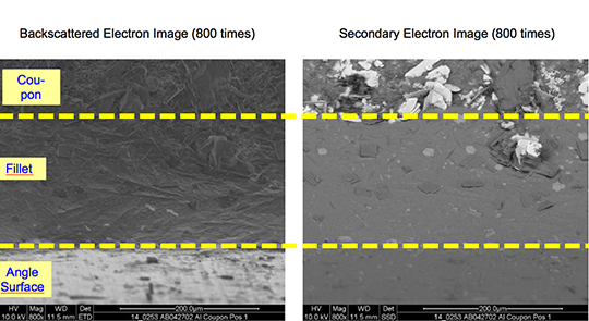
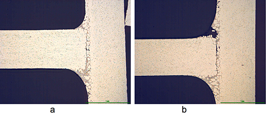
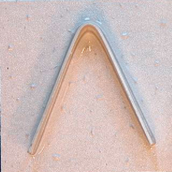
The angles from most of the AMAG specimens could be removed after brazing by pulling. Only a broken inner and outer fractured seam line was left – as can be seen below in picture 1 a.
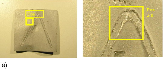
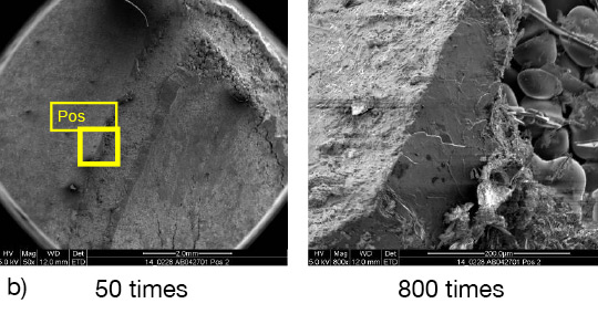
Picture 1: a) Photos, b) and c) SEM/EDX of NOCOLK® Cs Flux brazed sample (load 15 g/m²) Coupon 0.68% Mg, angle 0.68% Mg – angle removed by pulling
From the SEM analysis it is evident that a proper met-allurgical joint between base and angle has not been formed.
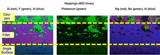
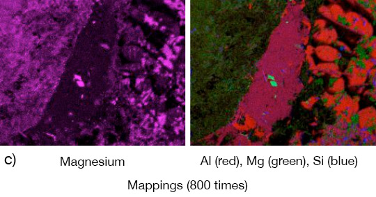
Picture 2: SEM/EDX analysis of aluminium ‘angle on coupon‘ brazed with KAlF4/BaF2 blend
There is flux residue present in the pulled apart fillet. This indicates that the liquid filler alloy was not capa-ble of pushing out completely the flux of the joint and it could be an explanation for the weakness of the fillet.
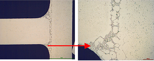
However, in case of the blend MD001212 LiCs24 with load 15g/m2 the joint structure is thorough as can be seen in picture 3 a).
Picture 3: Microstructures of the brazed joints
a) Flux MD001212, load 15g/m2
b) Flux MD001223, load 15g/m2
It is worth mentioning when connecting blocks are brazed to condenser manifolds often a high load of manually applied flux is used in order to overcome the high Mg content in the block material. For such a case using the mixture MD001212 would allow for having quite high Mg content in the block material, which can be required by the designers of condens-ers.
The total concentration of 1.36% Mg (joint interface) is probably too high, because for most brazing applica-tions, a flux load of 15g/m2 is impractical. Thus, we decided to reduce the level of Mg in our samples to half – i.e. to 0.68% – by switching to an AA1050 (Al 99.5%) angle. We also reduced the flux load to a more process-typical level of 5g/m². The results are listed in table 2:
| Flux Type | Load | Fillet visual validation | Comment |
|---|---|---|---|
| MD001212 LiCs24 | 5 g/m2 | 100% | good seam |
| NOCOLOK® Cs | 5 g/m2 | 87% | small joint |
Table 2: Brazing tests AMAG coupon (0.68% Mg)/Al99.5 angle
The structure of the joint cross section below (picture 4) obtained with flux MD001212 LiCs24 shows good quality.
Picture 4:Joint cross sections of alloys containing 0.68% Mg brazed with MD001212 LiCs24, load 5g/m2
To be continued…
- P Garcia et al, Solubility Characteristics of Potassium Fluoroaluminate Flux and Residues, 2nd Int. Alum. Congress HVAC&R, Dusseldorf (2011)
- P Garcia et al., Solubility and Hydrolysis of Fluoroaluminates in Post-Braze Flux Residue, 13th AFC Holcroft Invitational Aluminum Brazing Seminar, Novi (2008)
- J Garcia et al, Brazeability of Aluminium Alloys Containing Magnesium by CAB Process Using Cs Flux, VTMS5, 2001-01-1763 (2001)
- H Johannson et al, Controlled Atmosphere Brazing of Heat Treatable Alloys With Cesium Flux, VTMS6 C599/03/2003 (2003)
- Handbook of Chemistry and Physics; Ref. BaSO4: 0.0025 g/l
- U Seseke, Structure and Effect – Mechanism of Flux Containing Cesium, 2nd Int. Alum. Brazing Con., Düsseldorf (2002)
Approach to non-corrosive fluxes for further reduced residue solubility and improved magnesium tolerance
Technical Information by Ulrich Seseke-Koyro, Hans-Walter Swidersky, Leszek Orman, Andreas Becker, Alfred Ottmann
We split the article in four parts:
- Abstract and Basic Experimental Laboratory Procedures
- Reduced Flux Residue Solubility
- Improved Magnesium Tolerance
- Summary and Outlook
Reduced Flux Residue Solubility
The water solubility of standard NOCOLOK® Flux is 4.5 g/l, whereas for post-braze flux residue (pbr) it is 2.7 g/l. Post-braze residue of NOCOLOK® Li Flux shows a solubility of 2.2 g/l [1].
In the periodic table of chemical elements the group I fluorides have a reasonable low solubility (LiF: 2.7g/l [20°C]), but their Al-F-complexes much lower (Li3AlF6: 1.1g/l , K2LiAlF6: 0.3g/l with about 183 mg F-/l, K3AlF6: 2g/l), the group II fluorides (Alkaline Earth Fluorides “AEF”) show very low solubility (MgF2: 0.13g/l, CaF2: 0.016g/l, SrF2: 0.12g/l [25°C], BaF2: 0.12g/l [25°C]) [5]. Based on the facts of the dissolution behaviour of NOCOLOK® Li and the much lower solubility of the AEFs, we started investigating combinations of potas-sium fluoroaluminate fluxes with selected AEFs to combine the brazing characteristics of NOCOLOK® type flux with the very low solubility of AEF.
NOCOLOK® Flux consists of potassium fluoroalumi-nates with a specific ratio of KAlF4 and K2AlF5. Each of these compounds has different solubility. The combination of the (pure) compounds with different AEFs was of our main interest. We melted and pulverized the flux blends, dissolved them in a defined amount of DI-water and analyzed for K, Al and F.
The data achieved form these experiments is illus-trated in figure 1:
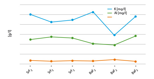
Fig. 1: Solubility of flux blends – melted and pulverized
(lines are used to illustrate differences of the blends)
Considering minor statistical variations, the results look quite reasonable, with the blend of NOCOLOK® Li/BaF2 showing the lowest K value. This observation can be explained by the low solubility of NOCOLOK® Li Flux. Of more relevance is the actual post-braze solubility (flux residue) on brazed Al surfaces. Interactions of base material and molten filler metal may have a more complex chemical impact on the solubility behaviour
The results from coupon brazing under laboratory conditions and the solubility of the flux residue can be seen in figure 2.
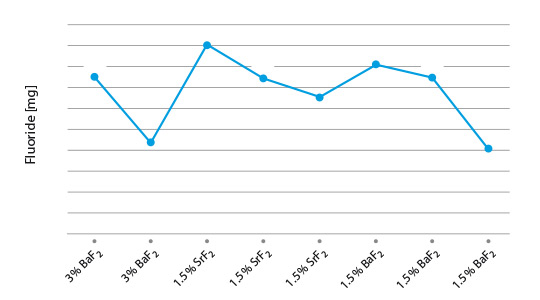
Fig. 2: Post-braze fluoride solubility of selected flux/ AEF combinations on Al coupons
(lines are used to illustrate differences of the blends)
Among the combination of NOCOLOK® type fluxes with diverse AEF additions, KAlF4/BaF2 shows the lowest residue F– solubility, i.e. 4mg/l. All our laboratory brazing tests with the samples showed the same good results like with standard NOCOLOK® Flux.
Corrosion comparison tests will be subject for future investigations.
To be continued…
- P Garcia et al, Solubility Characteristics of Potassium Fluoroaluminate Flux and Residues, 2nd Int. Alum. Congress HVAC&R, Dusseldorf (2011)
- P Garcia et al., Solubility and Hydrolysis of Fluoroaluminates in Post-Braze Flux Residue, 13th AFC Holcroft Invitational Aluminum Brazing Seminar, Novi (2008)
- J Garcia et al, Brazeability of Aluminium Alloys Containing Magnesium by CAB Process Using Cs Flux, VTMS5, 2001-01-1763 (2001)
- H Johannson et al, Controlled Atmosphere Brazing of Heat Treatable Alloys With Cesium Flux, VTMS6 C599/03/2003 (2003)
- Handbook of Chemistry and Physics; Ref. BaSO4: 0.0025 g/l
- U Seseke, Structure and Effect – Mechanism of Flux Containing Cesium, 2nd Int. Alum. Brazing Con., Düsseldorf (2002)
Approach to non-corrosive fluxes for further reduced residue solubility and improved magnesium tolerance
Technical Information by Ulrich Seseke-Koyro, Hans-Walter Swidersky, Leszek Orman, Andreas Becker, Alfred Ottmann
We split the article in four parts:
- Abstract and Basic Experimental Laboratory Procedures
- Reduced Flux Residue Solubility
- Improved Magnesium Tolerance
- Summary and Outlook
Abstract
For more than 30 years, potassium fluoroaluminates (NOCOLOK®) fluxes are already successfully used in controlled atmosphere brazing (CAB) of aluminium heat exchangers. Residues of these so-called non-corrosive fluxes have very low – but evident – solubility in water [1] [2]. In the discussion about corrosion of CAB produced aluminium heat exchangers, the flux residue solubility is an important parameter. There are concerns that – in addition to several other factors – fluoride ions (F–) potentially released from dissolved residue play a role in aluminium corrosion.
A theoretical option to address this point is the development of virtually insoluble flux. More realistic, however, will be fluxes with less soluble residues than the current compositions.
Some commercialised NOCOLOK® derivates, like NOCOLOK® Li Flux show already reduced solubility when compared to the standard product [1]. While investigating the chemical possibilities for further minimising the residue solubility and the release of F- ions, we have developed NOCOLOK® variants in combination with selected inorganic fluorides.
During this R&D project we also looked closely at the brazing properties of the new fluxes – with a focus on their performance for brazing of aluminium alloys with higher magnesium level. The current maximum magnesium range suitable for CAB with standard NOCOLOK® Flux is approximately 0.3%. Some improvement can be seen when using caesium-containing NOCOLOK® formulations (up to 0.5% Mg) [3] [4]. Some of the new fluxes we developed for further reduced residue solubility surprisingly show higher magnesium tolerance. This article summarizes the results of our laboratory work related to the development of fluxes with further reduced residue fluorides solubility and improved magnesium tolerance.
Basic experimental laboratory procedures
1. Lab brazing and alloy specimen setup
For experimental lab furnace brazing we used standard CAB brazing profile and 25 by 25 mm clad sheet coupons (single side) with angle on top. In case of the Mg topic an AMAG (Austria Metal AG) clad alloy (6951/4343) was brazed with an AMAG clad-less angle. Fluxing was done manually (flux load weight on precision scale, drops of isopropanol and homogenous spreading).
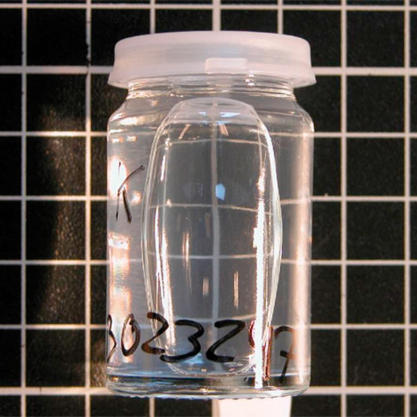
2. Solubility data generation
Coupon (3003/4343) with Al angle (Al 99.5%) were manually coated with a dedicated amount of flux blend and brazed as described in point 1. Brazed samples were placed in PET bottles and a defined quantity of demineralised water was added. Daily visual control and air exposure (by opening and closing the lid) was done.
To be continued…
- P Garcia et al, Solubility Characteristics of Potassium Fluoroaluminate Flux and Residues, 2nd Int. Alum. Congress HVAC&R, Dusseldorf (2011)
- P Garcia et al., Solubility and Hydrolysis of Fluoroaluminates in Post-Braze Flux Residue, 13th AFC Holcroft Invitational Aluminum Brazing Seminar, Novi (2008)
- J Garcia et al, Brazeability of Aluminium Alloys Containing Magnesium by CAB Process Using Cs Flux, VTMS5, 2001-01-1763 (2001)
- H Johannson et al, Controlled Atmosphere Brazing of Heat Treatable Alloys With Cesium Flux, VTMS6 C599/03/2003 (2003)
- Handbook of Chemistry and Physics; Ref. BaSO4: 0.0025 g/l
- U Seseke, Structure and Effect – Mechanism of Flux Containing Cesium, 2nd Int. Alum. Brazing Con., Düsseldorf (2002)
In recent years, the topic of what to do with wastewater from fluxing operations has gained a lot of attention in light of heightened environmental awareness and compliance. Years ago, wastewater from cleaning slurry booths, waste flux slurries etc. were simply diluted and dumped down the drain. Some manufacturers are still following this practice, but it is become less and less common. Today, the heat exchanger manufacturers are faced with what to do with wastewater more and more.
Some manufacturers collect the waste slurries and effluent from cleaning out the fluxing stations and allow the flux to settle out. The water phase is then decanted and collected until a sufficient volume is collected. At that point, a waste disposal company is called in to collect and treat the contaminated water. This is an expensive, but in many cases a necessary option. If the collected water is relatively clean and not contaminated with oil, it may be reused to top up flux slurries. The only problem here is that one must be certain that there are no other contaminants in the wastewater other than flux ions. If there are other contaminants (and there almost certainly will be), tests should be performed to ensure that these will not in any way interfere with the brazing process.
Solvay Fluor also developed a continuous process to reuse and recycle wastewater in a fluxing operation. It is based on the principles described above, only in a continuous fashion:
Lauzon, D.C., Swidersky, H.W., “Methods for Eliminating Wastewater from Flux Slurries in Non-Corrosive Flux Brazing”, VTMS 2001-01-1764, pp 649-654, 2001.
Dumping
With continuous use, a flux slurry will eventually become contaminated. So far, there is no data that correlates the level of accumulated contaminants with poor brazing. Therefore, it is better to be on the safe side rather than wait till the number of rejects rise due to a contaminated or dirty slurry. It is therefore recommended that a slurry should be dumped when there is visual evidence of contamination. If there is an oil slick floating on top of the slurry in the reservoir or when it is discolored, the slurry should be dumped and replaced with fresh slurry. Alternatively, to avoid misjudging the quality of slurry visually, the slurry could be dumped at regular intervals, especially if the manufacturer knows that the cleanliness of the heat exchangers entering the fluxing booth is not ideal. Experience will dictate how often the slurry should be dumped.
Note however that some heat exchanger manufacturers almost never dump their flux slurries or if they do it might be only once per year. This is only the case when the heat exchangers are very well degreased prior to entering the fluxing booth and efforts are made to avoid undue contamination of the slurry. Simply keeping the cover closed on the slurry tank reservoir will keep out airborne contaminants and lengthen the slurry life.
What to do with the used flux slurry is treated covered under wastewater.
Flux Recovery – Recycle and reuse?
Around the flux slurry preparation station or around the perimeter of the fluxing booth, there will inevitably be some flux on the floor. The inclination is to sweep up this flux and throw it into the flux slurry reservoir or back into the flux drum. This action should be avoided at all costs. Any flux that falls on the floor should be disposed of promptly. The reason is that there are too many contaminants in a manufacturing environment that can affect brazing or cause other damage. Cigarette butts, paper clips, dust, dirt, oil, paper and so on can all have very damaging effects to the flux delivery system and on the brazed products. If the flux is on the floor, dispose of it and do not reuse it.

Flux powder on the plant floor should be collected by vacuum cleaners equipped with high efficiency particulate air (HEPA) filters, dedicated central vacuum systems or a wet vacuum system. Avoid sweeping and the use of compressed air. Small wet spills may be mopped up. To remove large spills the floor should be hosed down with water. Waste and contaminated water must be disposed of in accordance with local regulations.