Schlagwortarchiv für: Flux Application

written by Leszek Orman, Radziszow / Poland; Hans-Walter Swidersky, Hannover / Germany

3  Results and discussion / Part 2

Corrosion resistance of the mock up samples was checked in the so called soaking test.  Exemplary structures are shown in fig. 4:


Fig. 4: Exemplary metallographic cross sections after 60 days of soaking (flux load 16g/m2, tube: HA 9170) 

Observation of metallographic structures did not allow for a univocal statement that there are certain differences between investigated parts. In none of the investigated cases a fin debonding process was observed. At longer time of soaking, intensive corrosion of fins could be observed. More details were obtained when measuring the thickness of the tube walls. These results are presented in fig. 5:
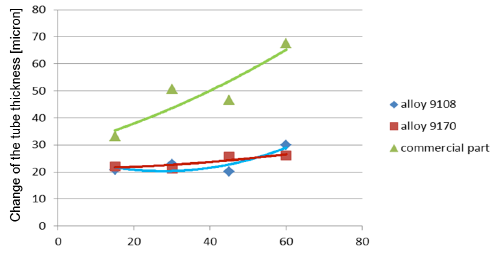

Fig. 5a:
Change in the tube wall thickness as a function of soaking time – Time of soaking [days] – Flux load 8 g/m2
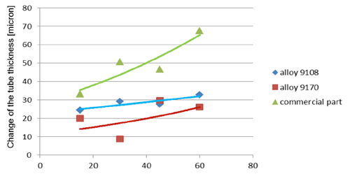
Fig. 5b: Change in the tube wall thickness as a function of soaking time – Time of soaking [days] – Flux load 16 g/m2

It seems that thinning of tubes at the beginning of the soaking test is quite rapid as compared to the period of soaking longer than 15 days.  In case of the NOCOLOK® ZnLi Flux, the maximum tube thinning is in the range of 30 microns.  The same maximum value for the commercial part is in the range of 65 microns.  There is no significant difference in the tube thinning between the two tested different alloys.

Industrial test

The industrial test was performed with condensers used for stationary application. However, they had a typical design as for automotive. In this case – since the standard production tube were not zinc coated – the testing was done using NOCOLOK® Li Flux.

Material of the tested part:
Fins: FA 6815 clad 4343 both sides
Tubes: HA9108
Manifolds: HA3905-R outside clad HA4045-D

Brazing was performed on industrial brazing line made of wet fluxer, dryer and Active Only (Seco/Warwick) brazing furnace.  Fluxing was done with NOCOLOK® Li Flux – concentration 13% for overhead spray and 43% for tube to manifolds joints.  The above concentrations were the same as for standard industrial production.  Also no changes were done in brazing parameters as compared to standard conditions.

Corrosion resistance of the brazed parts was checked by SWAAT (ASTM G85 A3).  In order to examine the parts after different times at SWAAT, a brazed part was segmented, and all the segments were tested in the same test chamber – but for different time periods.

Examination of the segments after 5 days in SWAAT did not reveal any significant progress of corrosion; however, after longer times, fin debonding was observed.  This examination did not show any differences between the parts fluxed with NOCOLOK® Li Flux and those fluxed with standard NOCOLOK® Flux.  More information was obtained when examining metallographic cross sections:
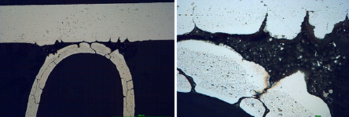

Fig. 6a: Structure of the samples brazed with NOCOLOK® Flux after 5 days in SWAAT 
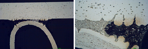
Fig. 6b: Structure of the samples brazed with NOCOLOK® Li Flux after 5 days in SWAAT

It can be observe that initially corrosion starts as intergranular attack on the fin material and as an intensive attack on the filler alloy. The filler is attacked selectively; firstly the alpha phase of the eutectic is removed.
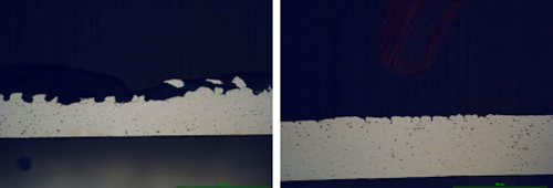

Fig. 7:
 Structure of samples brazed with NOCOLOK® Flux (left) and NOCOLOK® Li Flux (right) flux after 60 days in SWAAT

Already after 30 days of SWAAT, for both sample almost all the fins were detached from the tubes – thus the examination of the parts after 60 days of SWAAT was limited only to the tubes.

The surface of the tube in case of standard NOCOLOK® is corroded to a much higher degree than in the case of the part brazed with NOCOLOK® Li Flux.  The corrosion in both cases is initiated by intergranular attack; however later on it does not develop into pitting corrosion, but the removal of the tube material has laminar character.  It seems that NOCOLOK® Li Flux did not cause a change of the corrosion mechanism; it just delayed the corrosion processes.

The higher corrosion rate for samples brazed with standard NOCOLOK® Flux observed in the microscopic structures has been confirmed by measuring the tube wall thickness.  Results of those measurements (at least 10 measurements per point) are presented in fig. 8.  It should be worth noticing that the standard variation for the wall thickness measured after 60 days of SWAAT was 10.9µm for fluxing with NOCOLOK® Li Flux and 81.2µm for fluxing with standard NOCOLOK® Flux.  Such a large variation in the wall thickness in case of NOCOLOK® Flux would indicate that the “long life” capacity of the protection mechanism in this case was practically exhausted.
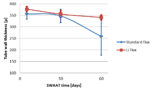

Fig. 8: Thinning of the tube wall during SWAAT

4 Conclusions

The experiment with the mock ups allowed for conclusions that there is no negative influence of NOCOLOK® Li Flux on the creation of Zn enriched sacrificial layer.  Presence of NOCOLOK® Li Flux in the mixture allowed for better protection of the sample parts against corrosion in stagnant water test.  One objective of stagnant water corrosion test is the simulation of stationary air conditioning unit humidity exposure.

It is possible to utilize in a flux mixture advantages of NOCOLOK® Zn and of NOCOLOK® Li.  Also as shown by testing with two different tube alloys, there is no significant difference in the tube thinning between different alloys.

Initial laboratory observations – that NOCOLOK® Li Flux improves resistance to corrosion in SWAAT condition – have been proven on industrial part.  Thus one option to increase the life time during SWAAT can be to use NOCOLOK® Li Flux.

Go to part 1

Literature

[1] A. Gray, H.W. Swidersky, L. Orman.
Reactive Zn Flux – an opportunity for controlled Zn diffusion and improved corrosion resistance.  AFC Holcroft 11thInternational Invitational Brazing Seminar, October 2006

[2] A. Gray, A. Afseth, H.W. Swidersky. The influence of residual flux level on the corrosion behavior of heat exchanger materials, ASST, May 2003

[3] Solvay Patent. WO10060869 A1 – Anti-Corrosive Flux – NOCOLOK®Li Flux, 2010

[4] Solvay Patent. WO11098120 A1 – Flux Forming an Insoluble Brazing Residue – Li Flux – Li3AlF6, 2011

[5] NOCOLOK®Li Flux New Brazing Flux with Improved Residue Performance

[6] NOCOLOK®Zn Flux – Technical Information

written by Leszek Orman, Radziszow / Poland; Hans-Walter Swidersky, Hannover / Germany

Abstract

In 2001 and in 2009 respectively, Solvay introduced two new fluxes for aluminium brazing: – NOCOLOK®Zn Flux (a ‘reactive flux’ – for the creation of precisely controlled sacrificial layers on part surfaces); and – NOCOLOK®Li Flux (for improving corrosion resistance of stationary air conditioning systems under stagnant water conditions).

When brazing with NOCOLOK®Li Flux, as validated on laboratory scale, some aluminium alloys show slightly better corrosion performance in SWAAT than parts brazed with standard flux.

On this basis, it was decided to investigate if a combination of NOCOLOK®Zn Flux and NOCOLOK®Li Flux can provide additional improvements in corrosion resistance.

Tubes of sample heat exchangers were coated with mixtures of Zn Flux and Li Flux – and brazed in an industrial furnace. Their corrosion resistance was checked by so-called soaking tests – i.e. by immersion in demineralized water over extended period of time.

In order to check the influence of NOCOLOK®Li Flux on corrosion resistance, some condensers were brazed under real industrial conditions, and their corrosion behavior was examined in SWAAT.

The results of this work indicate that a combination of NOCOLOK®Zn Flux and NOCOLOK®Li Flux can contribute to improved corrosion resistance at stagnant water conditions, and that NOCOLOK®Li Flux can delay corrosion attack in SWAAT.

1 Introduction

Corrosion resistance of heat exchangers exposed to different elements during service has been always one of the main concerns for the heat exchanger manufacturers and users. The most important methods for improving corrosion resistance of a given aluminium heat exchanger are:  selecting alloys for the exchanger parts in such a way that the galvanic potentials of the exchanger elements are properly balanced; creation of a sacrificial layer on a given part of the exchangers (usually tube surfaces); and coating the whole exchanger with a protective layer, which prevents a direct contact of the environment elements with the metal of the heat exchanger.

A common method for the creation of a sacrificial layer on the tube surface involves introducing Zn into the outer layer of the tube material.  Traditionally it is done by electro arc spraying of the extruded tubes with metallic Zn.  To improve the uniformity of the Zn enriched layer and to enable better control of the Zn diffusion profile, NOCOLOK®Zn Flux was developed [1].

With the flux on the aluminium parts to be brazed, a thin strongly adhering layer of post brazed flux residue remains on the surfaces after brazing.  Provided that this layer is uniform and covers all elements of the exchanger, it slightly improves corrosion resistance – acting as a barrier for element penetration [2]; however, for standard NOCOLOK®Flux this positive effect is not very strong.

Upon the introduction of all aluminium CAB produced condensers into stationary air conditioning systems, it was observed that the surfaces of such units – when exposed to stagnant water (for example from rain or condensation), can show signs of corrosion.  In response to that situation NOCOLOK® Li Flux was developed.  Reduced water solubility of NOCOLOK® Li Flux post braze flux residue has been attributed for slowing down corrosion rate of the brazed aluminium parts under stagnant water condition [3, 4].  Also it was observed that parts brazed with NOCOLOK® Li Flux (laboratory samples) show higher resistance to corrosion in SWAAT [5].  On this basis, it was decided to investigate whether a combination of NOCOLOK®Zn Flux and NOCOLOK®Li Flux can achieve further improvements of corrosion resistance, and if NOCOLOK®Li Flux can provide additional corrosion resistance for industrial parts in SWAAT.

2 Experimental

Determination of the flux mixture composition

In the first step of the experiment, brazing at industrial conditions of especially prepared mock-ups was performed (Fig.1). The primary task was to determine the correct proportion between the NOCOLOK® Zn Flux and Li cryolite (Li3AlF6). The mixture composition was established on an assumption that the lithium cryolite should react with K3AlF6(equation 2) in order to minimize the water solubility of the Post Braze Flux Residue [PBFR].  Thus the calculation was based on following reactions [1, 4]:

12 KZnF3 +  8 Al   →   12 Zn  +  6 KAlF4 +  2 K3AlF6                                (1)

Li3AlF6 +  2 K3AlF6   →   3 K2LiAlF6                                                           (2)

By adding the sides of equations 1 and 2 we obtain:

12 KZnF3 +  8 Al  +  Li3AlF6  →  12 Zn  +  6 KAlF4 +  3 K2LiAlF6             (3)

Substituting the atomic masses into equation 3, we obtain that the composition of the flux mixture should be:

NOCOLOK®Zn Flux – 91.7%; lithium cryolite – 8.3% by weight.  As stated in [6], a load in the range of 10 g/m2of Zn Flux (which corresponds to metallic level of Zn equal to 4g/m2) is sufficient for providing sacrificial layer on the substrate surface.  In order to envelope the above value for the current experiment 3g/m2and 6g/m2of metallic Zn load were chosen.  That corresponds to 8g/m2and 16g/m2of the NOCOLOK® Zn Flux + Lithium cryolite mixture.  Further on this mixture is called NOCOLOK®ZnLi Flux.


Fig. 1:  The assembled mock up with Data Pack thermocouples just before brazing

Materials used in experiment:

  • Flux: NOCOLOK® Zn Flux – 91.7% weight, lithium cryolite – 8.3% weight
  • Fins: HA 3968-K
  • Headers: HA 3905-R
  • Tubes, alloy 1: HA 9108
  • Tubes, alloy 2: HA 9170, both alloys coated on industrial machine (SAPA Precision Tubing) with NOCOLOK®ZnLi, load (8 and 16g/m2)

The fins, tubes and headers were manufactured by Hydro Aluminium Rolled Products.

Brazing of the mock ups was performed in industrial Active Only brazing line made by Seco/Warwick.  As measured by Data Pack®, the parts stayed at temperature over 580°C for about 5 minutes.

After brazing the Zn diffusion profile and resistance to the so called soaking test were evaluated.

3  Results and discussion

Mock up experiment

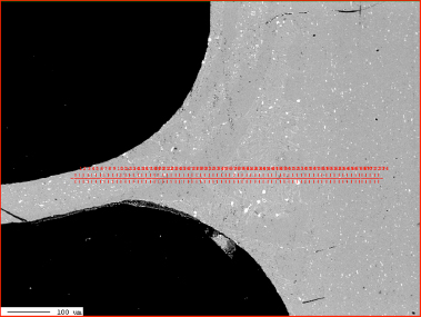
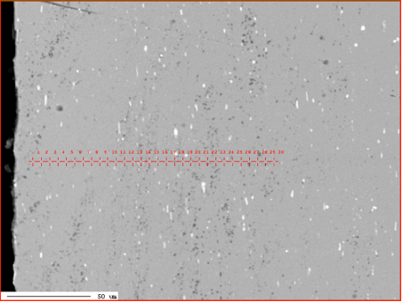
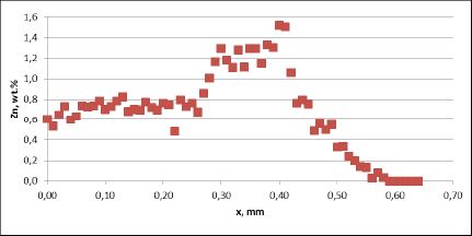
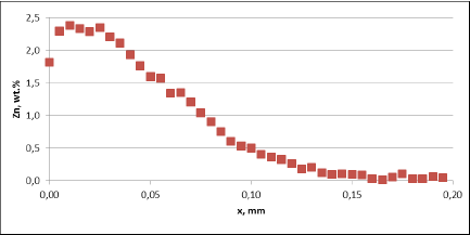
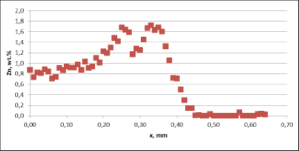
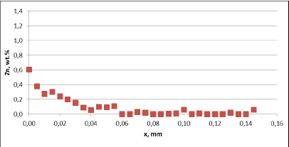
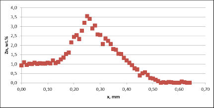
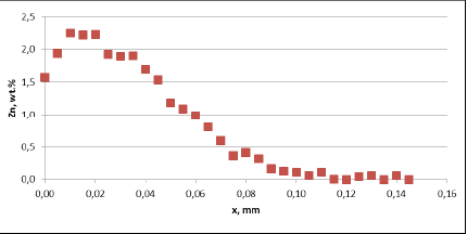
Zn diffusion profiles was measured by X-ray microprobe JXA 8230 made by JEOL. Applied accelerating voltage: 15kV with the beam current 30nA.  They were measured in two characteristic places: through the fin to tube joint and through the tube in the middle of the fin joints. This is shown in Fig. 2:


Fig. 2: Electron Back Scattered Image – example showing location of the analyses lines

Diffusion profile across the joint, Flux load 8g/m2, tube alloy HA9180
Fig. 3a:
  Zn diffusion profiles – as measured on the brazed mock ups, Diffusion profile across the joint, Flux load 8g/m2, tube alloy HA9180

Diffusion profile between the joints, Flux load 8g/m2, tube alloy HA9180
Fig. 3a:  Zn diffusion profiles – as measured on the brazed mock ups, Diffusion profile between the jointsFlux load 8g/m2, tube alloy HA9180

Diffusion profile across the joint, Flux load 16g/m2, tube alloy HA9170
Fig. 3a:  Zn diffusion profiles – as measured on the brazed mock ups, Diffusion profile across the jointsFlux load 16g/m2, tube alloy HA9170

Diffusion profile between the joints, Flux load 16g/m2, tube alloy HA9170
Fig. 3a: Zn diffusion profiles – as measured on the brazed mock ups, Diffusion profile between the jointsFlux load 16g/m2, tube alloy HA9170

Zn diffusion profiles – as measured on the commercial sample, Spot 1, Diffusion profile across the joint
Fig. 3b:
 Zn diffusion profiles – as measured on the commercial sample, Spot 1, Diffusion profile across the joint 

Zn diffusion profiles - as measured on the commercial sample, Spot 1, Diffusion profile between the joints
Fig. 3b: Zn diffusion profiles – as measured on the commercial sample, Spot 1, Diffusion profile between the joint 

Zn diffusion profiles – as measured on the commercial sample, Spot 2, Diffusion profile across the joint
Fig. 3b:
 Zn diffusion profiles – as measured on the commercial sample, Spot 2, Diffusion profile across the joint 

Zn diffusion profiles – as measured on the commercial sample, Spot 2, Diffusion profile between the joint
Fig. 3b:
 Zn diffusion profiles – as measured on the commercial sample, Spot 2, Diffusion profile between the joint 

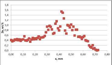
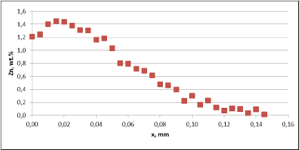
For all mock up samples the depth of diffusion profiles is around 120 microns.  The maximum level of Zn concentration for lower flux load is at the range of 1.2% to 1.4% – and for higher flux load is in the range of 2.5%. These values seem to be typical for tubes coated with NOCOLOK®Zn Flux. Also the maximum content of Zn in the fillet seems to be rather well balanced with the Zn concentration on the tube surface (Fig. 3a).

For comparison, the diffusion profile of a commercial part was also investigated. In this case the diffusion profiles show quite significant differences – both in the depth of diffusion and the maximum Zn concentration on the tube surface. Also the Zn concentration is higher for fin to tube joint (Fig. 3b). This observation seems to be consistent with a well known fact that electric arc Zn coating is not uniform having places with high and low zinc load.

Go to part 2

Literature

[1] A. Gray, H.W. Swidersky, L. Orman.
Reactive Zn Flux – an opportunity for controlled Zn diffusion and improved corrosion resistance.  AFC Holcroft 11thInternational Invitational Brazing Seminar, October 2006

[2] A. Gray, A. Afseth, H.W. Swidersky. The influence of residual flux level on the corrosion behavior of heat exchanger materials, ASST, May 2003

[3] Solvay Patent. WO10060869 A1 – Anti-Corrosive Flux – NOCOLOK®Li Flux, 2010

[4] Solvay Patent. WO11098120 A1 – Flux Forming an Insoluble Brazing Residue – Li Flux – Li3AlF6, 2011

[5] NOCOLOK®Li Flux New Brazing Flux with Improved Residue Performance

[6] NOCOLOK®Zn Flux – Technical Information

Additional information to the Article Flux Application: Electrostatic Fluxing

In dry flux application, the flux powder is electrostatically charged (typical voltage is ~ 100 kV) and applied to a grounded work piece. An electrical field results in flux deposition of the work piece. In practice, anisotropic distribution of the electric field can influence the homogeneity of powder coverage. At edges powder may accumulate, while penetration of powder into deep/thick fin packages (e.g., in case of double row tubes) can be limited by the Faraday cage effect.

Flux powder is electrically charged in the gun. However, it loses charge relatively fast when it hits the grounded heat exchanger. Therefore adhesion of the flux on the work piece is established rather by relatively weak Van der Waals forces than by electrostatic forces. Fine flux particles adhere better on the surface – but they are more difficult to operate with in the dry powder feeding system.

The relatively fine flux particles are more difficult to handle in dry powder feed systems compared to coarser paint powders – therefore the equipment used for electrostatic flux application is adapted to meet the specific requirements. Venturi pump, hose diameter, air flow and spray nozzle suitable for flux application are designed to minimize the possibility for powder buildup and clogging in the system. Powder transport within the hose system and the spray nozzle is further enhanced by introduction of additional air streams. The direction of the powder flow should always be from top to bottom. Sharp changes in flow direction must be avoided. In critical areas additional vibration units are installed to avoid powder buildup.

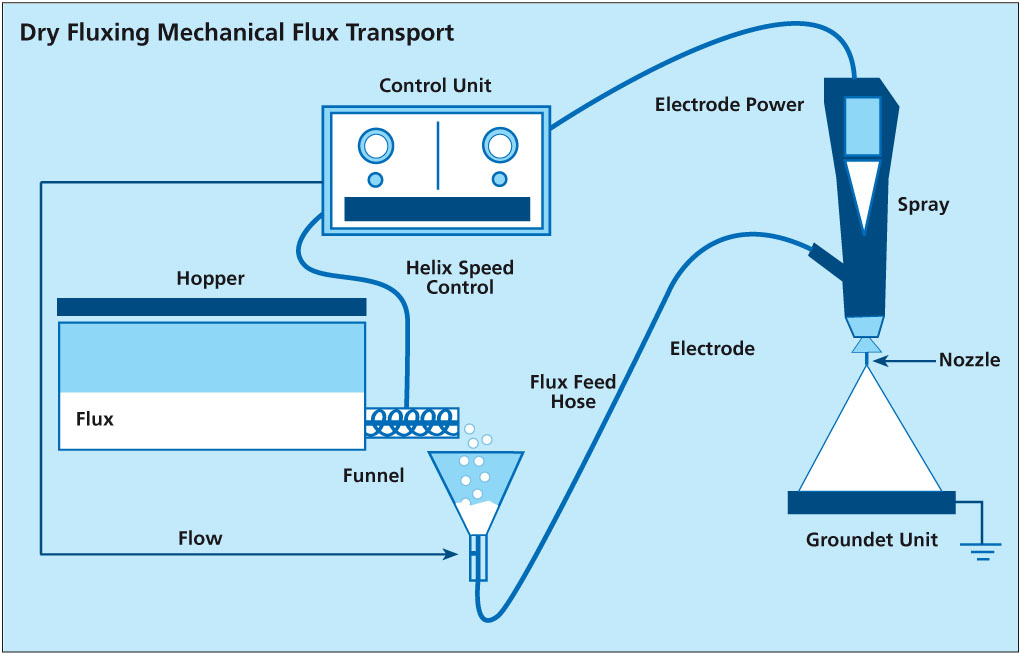
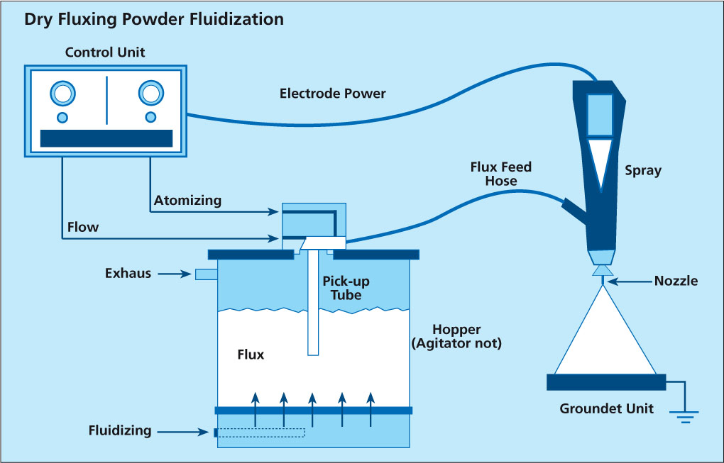
There are two types of powder feed systems established on the market (see the illustrations in the article):

The first type starts with the flux powder being fluidized in a fluidization vessel by compressed air that is fed through a porous membrane at the bottom of the fluidization vessel. The air going through the flux makes it behave like a fluid, since the powder is essentially diluted with air. A pick up tube attached to a Venturi pump is extended into the fluidized flux. Powder dosage is controlled by the volume of air flow through the pump. To optimize fluidization the vessel may additionally be equipped with a stirrer.

This type of feed system works perfectly well for classic electrostatic paints powders that are easy to fluidize, however, it may be difficult to establish a stable fluidization with ’standard‘ flux powder (i.e. the flux powder quality offered for wet/slurry-based flux application).

Fluctuations in density of the fluidized bed can result in inhomogeneous spray pattern (splashing) and might be a source for flux buildup within the system.

NOCOLOK® Flux Drystatic is optimized to minimize the challenges of powder feeding, while providing sufficient fine particle fraction for good adhesion properties.

The second type of powder feed system works on the principle of feeding the powder by a rotating helix screw (see the illustrations in the article above). Because of the mechanical displacement of the flux powder from the hopper, such devices minimize fluctuations of flux powder flow.

Most mechanical type of dry flux feed systems work with standard quality NOCOLOK® Flux as well as with special ‚Drystatic‘ grade NOCOLOK® powder.

To achieve flux distribution patterns for specific process needs (e.g., higher flux loads in tube to header areas, coating from both sides of thick cores), multiple spray nozzles are arranged for deposition of the necessary flux load at different locations of the heat exchanger.

Dry fluxing booths must be equipped with a filter system to collect the overspray. The overspray material is recycled within the booth. To avoid accumulation of impurities within the recovered flux, it is necessary to take care of the booth environment (i.e. avoid dust, fumes, and high humidity level) as well as for the quality of the compressed air used. Contamination introduced by the heat exchangers or the transport belt must be prevented as well.

Due to the relatively weak flux adhesion (compared with wet- or paint- application methods), handling of dry fluxed parts should be done with special care to avoid flux fall off, especially at higher flux loads. To reduce flux fall off, some users perform electrostatic fluxing on heat exchangers with evaporative oils still present on the surfaces. Thermal degreasing in this case takes place after fluxing – just before the parts enter the brazing furnace.

1. Preparation and Application

This article provides information about the application of binder systems for NOCOLOK Flux.

Solvay offers three concepts for flux binder application:

  • NOCOLOK Binder (water-soluble) / NOCOLOK Thickener (water-soluble)
  • NOCOLOK System Binder (water-based)
  • NOCOLOK Flux plus Binder Mixture (water-based)

These products can be used in water-based NOCOLOK Flux slurries to improve flux particle adhesion. This is of particular interest for fluxing of pre-formed components prior to assembly in order to reduce flux fall-off and dust formation. Binders are also helpful to pre-coat certain areas with specific flux loads. All binder mixtures can be applied on external and internal surfaces.

During the brazing cycle, these binders will completely evaporate (mostly between 350 and 400°C). When used as described below, there will neither be detrimental interactions between the binder and the flux, nor between the binder and the aluminum surfaces. Trials have shown that even at four-times the standard flux load with a binder mixture there was still no surface discoloration after brazing.

2. General Comments

The surface areas to be coated with binder mixtures must be free of lubricants, oils, dirt, and dust. Means of application include spraying, dipping, and brushing.

All NOCOLOK Flux binder mixtures can be applied by spraying with a suitable spray gun (1.4 mm – 1.6 mm) at approximately 3 – 5 bar pressure.

The surface temperature should be at least 10°C.

When binders are used for flux application, the recommended flux load for good brazing results is the same as it is for the standard process (i.e. between 3 – 5 g/m2). The thickness of the binder coating is usually between 10 – 30 μm.

Drying can be done in air – requiring approximately 15 – 20 minutes at room temperature for the coating surface – and 50 – 60 minutes before the parts can be handled. Oven and forced convection drying is feasible too: at 50 – 80 °C, parts will dry within 5 – 20 minutes.

Please refer to the MSDS for detailed information regarding the safe handling of the product.

3. Preparation of Binder Mixtures

For all binder concepts and preparations, the mixtures should be prepared or opened immediately before consumption.

To prepare a mixture free of agglomerates and to achieve best coating results, the following procedures must be observed for either binder concepts:

  • NOCOLOK Binder / NOCOLOK Thickener
    • 45 parts (wt%) de-ionized water (as used for preparing standard flux slurries) is mixed thoroughly with
    • 15 parts (wt%) NOCOLOK Binder (water-soluble) and
    • 5 parts (wt%) NOCOLOK Thickener (water-soluble).
    • Once the first three components are completely homogenized,
    • 35 parts (wt%) NOCOLOK Flux powder are added successively under continuous agitation.
  • NOCOLOK System Binder
    • NOCOLOK System Binder (water-based) already contains the binder and thickener component as well as water. Consequently, only NOCOLOK Flux powder must be added.
    • 65 parts (wt%) NOCOLOK System Binder (water-based) plus
    • 35 parts (wt%) NOCOLOK Flux.
  • NOCOLOK Flux plus Binder Mixture
    • NOCOLOK Flux plus Binder Mixture (water-based) is a ready-for-use preparation containing NOCOLOK Binder, NOCOLOK Thickener and NOCOLOK Flux powder.

If necessary, the mixtures can be passed through a sieve prior to use. This will remove any potential agglomerates.

Prior to use the flux powder in the mixture must be suspended. The thickener will prevent the flux powder from settling too fast, however, when stored for some time or diluted, the mixture must be well shaken before spraying.

The binder component is activated by oxygen from air. Once sprayed and dried, the product cannot be recycled or reused.

Any remaining flux / binder mixture should be stored in an airtight and sealed container. We recommend consuming the mixtures within one week after mixing.

4. Additional Information:

  • NOCOLOK Binder, -Thickener, and –System Binder are compatible for standard NOCOLOK Flux, -LM Flux, -Cs Flux, and -Sil Flux. They are not suitable for NOCOLOK CB Flux and -Zn Flux due to chemical reactions between these fluxes and the ingredients.
  • The formulations (mixing ratios) provided in Solvay’s technical information sheets and brochures are intended as general recommendations – They provide the best basis for automated spray application and have been tested with good brazing results.
  • The recipes can be adjusted to specific application needs by changing the mixing ratios within certain ranges.
  • A well balanced ratio of binder and thickener to flux in the mixtures is important for good brazing performance:
  • Higher binder ratios result in a harder coating layer and stronger flux adhesion. But they require more care for the binder removal step.
  • Very high binder and/ or thickener ratios increase the organic content in the mixture – which may result in carbon residues (discoloration) after brazing.
  • It is possible to reduce and/ or to increase the water content of the mixtures – resulting in higher respectively lower viscosity.
  • Water dilution will cause less wetting action and reduced adhesion.
  • A surfactant (wetting agent) is part of the binder formulation – providing uniform coating, and – compensating (to some extent) for surfaces not cleaned prior to application.
  • Thickener is used for adjusting the viscosity and to keep the flux powder longer in suspension – This provides better performance in spray application. Nevertheless, formulations can be prepared and used without the addition of thickener.
  • Cleaning before binder-based flux application is recommended – but not mandatory.
  • A clean surface can be coated more easily and the flux adhesion will be better.
  • Residual oils and lubricants are reducing binder activity and require higher flux load.
  • Higher surfactant levels can compensate for some contamination – but result in more foaming.

5. Binder Flux Mixing Ratios

  • The standard composition is 35% NOCOLOK Flux, 15% NOCOLOK Binder, 5% NOCOLOK Thickener and 45% water. If a product with lower flux ratio is wanted (i.e., with only 10% flux), the composition must be modified. Right now, we are proposing 10% flux, 8% binder, 2% thickener and 80% water. There is only limited experience with this composition, and we are a little concerned. The reasons for our concerns are as follows:
    • With 35% flux, the ratio of flux to binder/ thickener on the surface of the headers is sufficient to combat the effects of the high organic content. Also, 15% binder has reasonable adhesion characteristics.
    • At 10% flux, the ratio of flux to binder/ thickener must be modified; otherwise there may not be sufficient flux to combat the high organic content. This is why we propose to reduce the binder and thickener to 8% and 2%, respectively. In other words, too much binder/ thickener and not enough flux may lead to black deposits on the headers after brazing and/ or difficulties in brazing.

6. Warehousing Considerations and Shelf Life

  • Under standard storage conditions, the shelf life is up to 12 months and probably longer. Standard storage conditions means that the product was stored at less than 30°C, as suggested in the MSDS.
  • The binder product can be stored at a temperature higher than 30°C, but the shelf life will shorten due to premature aging. Therefore, we recommend that the binder products be consumed within six months, if the storage temperature is a constant 40°C. This is not based on experimental data, but on general knowledge of water based polymer systems and adhesives. Any product stored at a temperature higher than 40°C should be consumed more quickly.
  • Under no circumstances should the binder products, in their original packaging, be exposed to a temperature of 60°C or above. We suspect that polymerization will occur, agglomerates will form and the performance will drop.

7. Thermo-Gravimetric Analysis (TGA) for Binder Flux

Please refer to the flyer “NOCOLOK Flux Application with Binders”.

8. Recommendations for Reducing Costs

  • Is not possible to only mix the binder, thickener and flux and just add the water on site. Without the water, the flux/ thickener/ binder mixture forms a rubbery-like substance that is very difficult to work with.
  • The least expensive option is to purchase the binder and thickener separately and do mixing of all ingredients on site. The most convenient option is to have a ready-mix, ready-to-use product supplied.
  • Please see above for additional recommendations for mixing.

Summary

The article was written on the basis of frequently asked questions from companies which either wanted to start a new all-aluminium brazing production of heat exchangers or wanted to convert from copper and aluminium mechanical assembly design to all-aluminium brazed parts. The questions were grouped into three main categories: Equipment (emphasis on assembling process), Process (emphasis on different fluxes and fluxing methods) and Corrosion.

Specific production challenges are also presented, which are important not only to newcomers of all-aluminium brazed heat exchangers, but to established companies as well. These include typical brazing problems such as managing leaks and the basics of brazing copper to aluminium. These topics are discussed by their relevance to the brazing parameters and their role in successful brazing.

Content:

  1. Introduction (in this issue)
  2. Equipment (in this issue)
  3. Brazing process (in August issue)
  4. Brazing copper to aluminium (in September issue)
  5. Corrosion resistance (in September issue)
  6. Summary (in September issue)

1. Introduction

Brazing Furnace

Increasing environmental concern has identified the air conditioning and refrigeration industry as one of the contributors to the greenhouse effect and ozone depletion.

Accordingly to [1] 15% of all electricity consumption in the developed world is used by the air conditioning and refrigerator industry. Increasing the efficiency of these heat transfer systems has the positive impact of decreasing electricity consumption and therefore the overall emission of CO2. The advantages of all aluminium brazed condensers in an air conditioning system are well described in [2]. For example one such case study [3] allowed for saving about 2700 USD during 6 months. The above advantages are currently well recognized by both the air conditioning manufacturers and their end users. It is our observation that the majority of the companies in the HVAC industry which have started or are about to start production of aluminium brazed heat exchangers have only limited experience with aluminium brazing; therefore providing them with maximum possible technical assistance from the supplier side is of high importance.

This article was written on the basis of our contacts with such companies having an aim to offer some assistance to all newcomers and companies facing some troubles with their new type of production.

2. Equipment

In most cases, the first question from a company that wants to start a new aluminium brazing activity is: “What kind of furnace should I buy?”

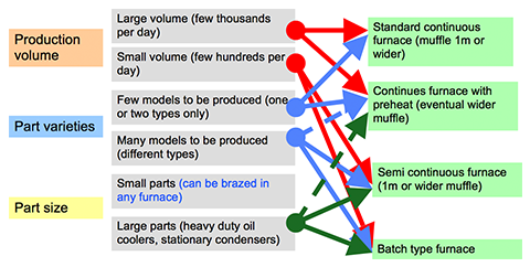
It is a complex issue which mainly depends on size of the products, its diversity and overall planned production volume. The general principles for the choice of the brazing furnace are shown in Fig. 1. It should be pointed out that the furnace manufacturers will make a brazing furnace customized to particular requirements of a given client.

Fig. 1: Basic principles for brazing furnace choice

Fig. 1: Basic principles for brazing furnace choice

Assembling units

In many cases the companies which are starting production of all aluminium brazed heat exchangers have been producing copper brazed heat exchangers. Therefore the natural question is: ”Can I use the same equipment which is used for copper units?”

The straight forward answer is: No! Aluminium requires high precision for assembling (recommended gap size is 0.1 to 0.15mm), which is hardly ever achieved for brazing copper parts. Also one should remember that any copper contamination on aluminium can cause catastrophic brazing failures (holes).

The process of component assembly can be done on a simple manual stacker or on machines with varying degrees of automation through to fully automated units. The level of automation should be mainly determined by the planned production volume, but also other factors such as local labour costs should also be considered.

Basic requirements for a manual assembling unit:

  1. Cores must be assembled on a perfectly flat heavy steel plate
  2. After laying out the tubes and fins, the tubes must be pushed precisely into position determined by the slots in the headers.
  3. To secure the above requirement:
    1. movement of the pusher must be allowed only in one direction (no side or up movement),
    2. travel distance must be accurately controlled – e.g. by mechanical block on the pusher,
    3. it is useful to have a special distances between tubes to secure the right spacing for each header slot,
    4. the vertical alignment of the tubes must be secured either by steel plate or by hammering the tubes with a special pad.
  4. Threading the headers on the tubes should be done in one single action which does not allow for any side or vertical deflection of the headers.
  5. After threading the headers the fixtures should be assembled and the tube pusher released.

The process of the part assembly is invariably connected with fixtures; these are the steel elements which hold the parts together during brazing and then removed after brazing. The most frequently asked question is: ”What should be the design of the brazing frames/fixtures?”

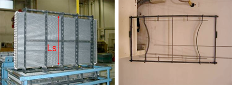
Basically there are rigid and elastic designs which allow for some expansion when the core is heated. For larger cores elastic design is preferred. This type of fixture is reusable, also known as a permanent fixture and can go through the brazing cycle several hundred times. Apart from that we could use single usage fixtures, known as disposable fixtures and these include steel wire and steel bands. The multi-use fixtures must be made of stainless steel and in most cases the single use fixtures are usually made of ordinary low carbon steel.

Fig. 2: Example of rigid and elastic fixtures

Fig. 2: Example of rigid and elastic fixtures

When designing the length of the fixture (distance marked in red as Ls in fig. 2, one must remember thatthere is a difference in thermal expansion coefficient between aluminium and steel. To compensate for this, the following assumption is made: The length of the steel fixture at brazing temperature must be equal to the nominal width of the aluminium exchanger at brazing temperature. On this basis, an equation can be used describing the linear change of dimensions with temperature.

Ls(1 + αstΔt) = Lo(1 + αalΔt)

Where:
Ls – length of steel fixture,
αst – thermal expansion coefficient for the fixture material,
αal – thermal expansion coefficient for aluminium,
Δt – Increase of the part temperature during brazing,
Lo – Nominal width of the part.

As an example, for a part having width of 900 mm and nominal tube spacing of 8 mm, solving this equation and taking into account the fact that after assembly there must be some pressure exerted by the fixture on the part, the length of the fixture should be 907.5 mm and the fin height 8.08 mm. The longer steel fixture is compensated by the increased fin height. It also means that after assembly the part will have a slightly barrel-like shape (bowed out at the sides).

The question: ”What final checks are required for brazed parts?”is also connected to equipment purchases. All brazed parts must be checked for leak tightness. The most simple method is the so called “under water test”. In this case the part is pressurized with air and lowered into a water bath to look for bubbles. However some end users require more accurate and reliable methods. In the automotive industry it is common to check condensers for leaks with high pressure and extremely sensitive helium leak detection devices.

Each product should be accepted by the end user. In every case the scope of acceptance tests should be agreed to between the manufacturer and the end users. Typical tests include burst pressure, thermal cycling and of course standard ones for heat transfer efficiency and pressure drop. As a general rule it can be said that all aluminium parts should meet all the requirements applied to copper/brass parts.


References:

1. Hans W. Swidersky, “Brazed Aluminium Heat Ex-changers for the Refrigeration and Air Conditioning Industry”, APT Aluminium News, 1-2009

2. Bjørn Vestergaard, “Brazed Aluminium Heat Ex-changers – Ask for the inexpensive features”, Seminar “Aluminium Process-Technology for HVACR Industry” Vienna, March 21st-23rd, 2007

3. Case Study – Harris County Sheriff’s Building, “Carrier Turn to the Experts” 2006 Carrier Corporation 05/06 04-811-10206

Will be continued…

This technique, also known as dry fluxing is gaining popularity as an alternative fluxing practice and therefore will be described here in some detail. Dry fluxing is a technology whereby the flux is electrostatically charged and applied to a grounded work piece, in our case a heat exchanger or individual heat exchanger components. The electrostatic attraction causes a layer of flux to be deposited on the work piece. A typical flux application system consists of a powder feed system, the electrostatic spray gun, the gun control unit, the grounded work piece and finally the flux recovery system.

The advantages of such a system over conventional wet fluxing are evident. Since the flux is applied dry, there is no need to prepare flux slurries, hence no need to monitor flux slurry concentrations. There is also no wastewater generated therefore more environmentally friendly. The dehydration or dry-off section of the furnace may be eliminated since the heat exchangers enter the furnace already dry. However, one must keep in mind that this is a relatively new fluxing technique and there are some minor drawbacks. Flux adhesion is not as good compared to that of wet fluxing. The flux also tends to accumulate on the leading edges of the heat exchanger and because of the Faraday cage effect, may have some difficulties in coating into corners or more specifically, in tube to header joints.

Powder Feed Systems
Presently, there are two types of powder feed systems on the market. The first type begins with the flux being fluidized in a hopper. Dry compressed air is fed through a porous membrane in the bottom of the hopper. The air rising through the volume of flux makes it behave like a fluid since the powder is essentially diluted with air. A pick up tube attached to an air pump is extended in the fluidized flux. Powder flow is then regulated by controlling the air-flow to the pump which is then delivered through the feed system to the spray gun. This type of feed system works perfectly well for powder paints. However, the flux has very different physical characteristics than powder paints (particle size, morphology) and so is difficult to fluidize. This must be taken into consideration when the manufacturer designs a powder feed system that relies on fluidization.

Dry Fluxing – Mechanical Flux Transport

The second type of powder feed system works on the principle of mechanical delivery or positive displacement. This means that the powder feed rate to the air pump is controlled by a screw or auger. The flux is contained in a main feed hopper and delivered mechanically at a controlled feed rate to the air pump. Powder flow is thus regulated by controlling the auger feed rate. This powder feed system does not rely on the flux being fluidized. Nonetheless, modifications over conventional mechanical powder feed systems are still necessary to overcome the differences between the flux characteristics and conventional powder paints.

Dry Fluxing – Powder Fluidization

Japanese heat exchanger manufacturers have used the technique of dry fluxing for many years now. Within the last few years, North American and European manufacturers have also installed electrostatic fluxing stations. Experience with this technique is being accumulated at a rapid rate, given that the equipment manufacturers and flux suppliers are taking an active role in improving the technology.

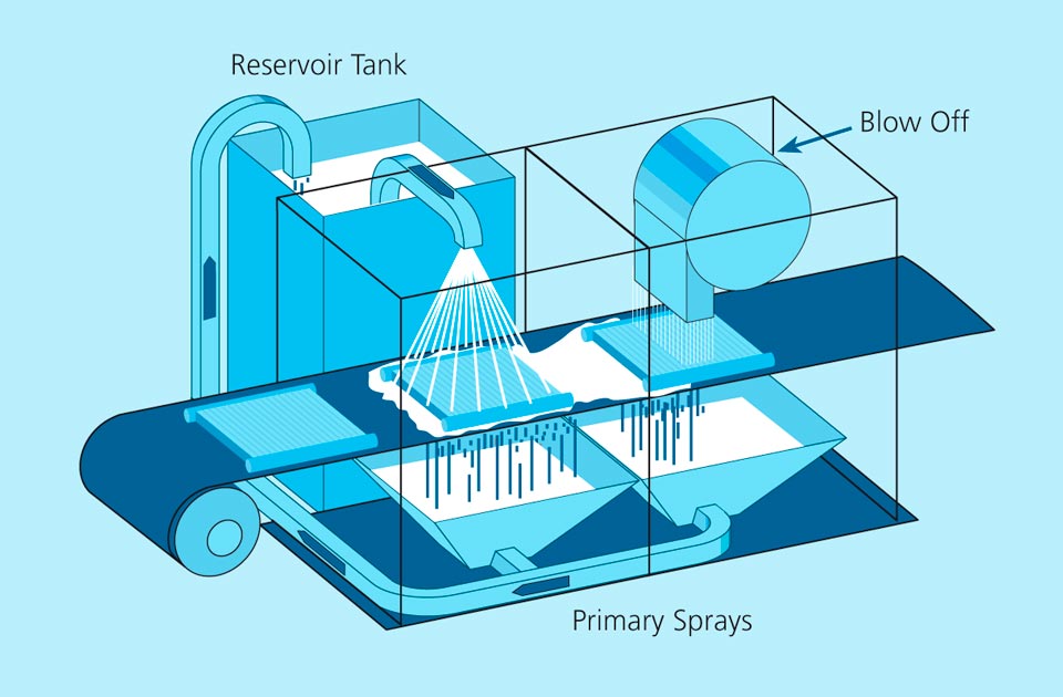
In its simplest form, a slurry is held in a reservoir tank and continuously agitated to prevent settling. The slurry is pumped, usually with air-diaphragm pumps to the flux slurry cabinet where the heat exchangers moving on a conveyor are sprayed with the slurry. After spraying, the excess flux slurry is blown off in a separate chamber with high volume air. The over spray and blown off slurry is recycled back to the reservoir tanks, again using air-diaphragm pumps.

Depending on the sophistication desired, a second flux spray chamber may be installed after the first chamber to deliver a higher concentration slurry to problem areas such as tube to header joints in condensers and radiators. This second spray chamber would have a separate flux delivery system and a separate reservoir tank to contain the higher concentration flux slurry.

The components of the flux delivery system including reservoir and agitators should all be constructed of stainless steel or chemically resistant plastics (nozzles for instance). There should be no mild steel or copper containing components – includes brass or bronze – in contact with the flux slurry. The schematic below shows the components of a generic fluxing station:

Wet Fluxing

Note that splashing will occur inside the fluxing cabinet and cause an accumulation of dried flux on the walls. Therefore the cabinet is washed with water periodically to remove this accumulated flux. The frequency of this maintenance operation is up to the manufacturer, but could be anywhere from once per shift to once per month.