Schlagwortarchiv für: B-tube

Brazing Issues

Folded tubes (or B-type tubes) for radiators have been developed several years ago. There are slightly different designs patented by most of the heat exchanger manufacturers.

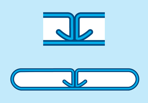
Below illustrations show three different B tube designs:
B-TUBES

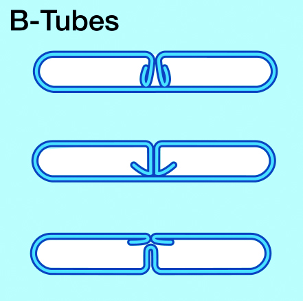
The folded tubes are produced from brazing sheet coils by a multi-step roll forming process – bringing the sheet gradually into a “B” shape. B-tubes have certain advantages – particularly regarding strength. The folded ends of the tube sheet are brazed inside the tube, which creates a very robust bridge between the walls. This results in higher burst pressure resistance.

The B tube roll forming process replaces the tube seam welding procedure. Standard flat radiator tubes are seam welded on one side – while folded tubes are joined during brazing. It is a general observation that folded tubes (“B-tubes”) are more difficult to braze (when compared with seam welded tubes).
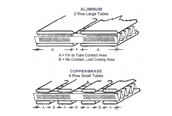
Some of the problems are related to flux coverage. Other difficulties are related to erosion effects due to the fact that there is more filler metal available from folded tubes than from welded tubes. One common feature of all folded tubes designs is the presence of a triangular gap or “delta” between the flat exterior portion of the tube wall surface and the fin convolution. This delta is created by the presence of the folds in the tube. This is a common failure site at the tube to header joint because there is not enough filler metal at the joint to allow for proper fillet formation.

In order to avoid troublesome inner tube fluxing and to minimize the level of flux residue in the cooling loop it has become more and more common to flux the tube folds (the so called leg) at the folding machine using a needle like dispenser which places a thin bead of flux paste along where the tube leg touches the tube inner surface in the subsequent folding operation. A specially formulated flux paste is required for such operation. Solvay offers for this purpose several formulations with different flux concentrations, viscosity ranges, and additives.

Another common feature with folded tube designs is that the fin-to-tube-joints are consistently larger on the folded tube side than on the non-folded side of the tube. This is attributed to the path created by the fold in the tube which allows the filler metal to flow from the header, up the tube and from the tube fold panels up into the fin to tube joint.

The dominant phenomenon present in brazing is capillarity, i.e. the force which draws the filler metal into the joints. A heat exchanger core may be considered as a complex matrix of capillary sites. Now, in a non-folded tube design, all the joints are considered separate and autonomous, that is none of the joints are connected. For the most part then, filler metal is drawn into the fin to tube and tube to header joints from the immediate area surrounding the joint.

When a folded tube is added, many of the previously separated joints become connected and inter-dependent. The fin to tube joints on the side of the tube fold are now in direct contact with the seam along the fold of the tube, which is also in contact with the tube to header joint at the header slot. Now, the heat exchanger has an extended zone to draw filler metal from, as the available clad for the fin to tube joint now extends throughout the entire length of the tube seam and even includes the header. During brazing, the center of the core will heat up faster (lighter weight compared to the heavier thermal mass of the headers and side supports) and creates a temperature gradient. The filler metal from the header is able to travel down the seam throughout the length of the seam, depleting the area around the tube to header joint of valuable filler metal. The result is smaller tube to header joints with a greater risk of failure and large tube to fin joints on the folded side of the tube.

One way to reduce the flow of filler metal along the seam resulting in saturation of the tube to fin joints is by putting Mg in the fin. This goes back to the principle of competing joints, where the joint with more Mg will draw less filler metal. By adding a small percentage of Mg in the fin yet keeping it brazeable, the wettability of the fin to tube joint is slightly reduced. The fin-to-tube-joints neither draw up all of the available clad from the headers nor from the tube seams. The clad no longer runs up the tube. Reduced wettability forces the clad to stay in the tube seam and in the tube to header joints.
If problems are observed with excessively large tube to fin joints on the folded tube side and/or if the tube to header joints are small and commonly fail due to a lack of filler metal, it may be considered to use fins with more Mg – to take advantage of the features mentioned above.

Technical Information by Daniel Lauzon

Manufacturing Processes

By the early nineties, aluminum had already almost completely replaced copper/brass in radiators at the Ford Motor Company. Ford had gone through mass production of mechanically assembled radiators starting in 1982 and introduced vacuum brazing in 1983. In 1989, Winterbottom reported,

…”the manufacturing capability and the superior corrosion resistance of aluminum was well established, and the competition between copper/brass and aluminum in the radiator application essentially ended.” (5)

By the mid-nineties, vacuum brazing was becoming less popular due to its high maintenance furnaces and less forgiving nature. Vacuum brazing was giving way to the more popular noncorrosive flux brazing process, also known as Controlled Atmosphere Brazing or CAB. Today, CAB brazing is the preferred process for manufacturing automotive heat exchangers worldwide. In Solvay’s estimate, there are now more than 600 CAB brazing furnaces in the world with more than 100 more in plan.

No discussion on the differences between copper/brass and aluminum radiator manufacturing processes would be complete without bringing up the topic of CuproBraze®. It is a new process for manufacturing copper/brass radiators developed by the International Copper Association (ICA) in conjunction with Outokumpu Copper Strip AB of Sweden (6). This process was surely developed to combat copper’s decline in the automotive heat exchanger markets and does appear to offer many advantages over the traditional copper/brass “soft-soldering” technology. But alas, no in-roads have been made in passenger vehicle radiators and the new technology is has found a niche in some truck and off-road vehicle markets.

Environmental and Recyclability Considerations

From an environmental perspective, there are no special considerations for adopting the noncorrosive flux brazing process. Unlike conventional Cu/brass radiator technology, there are no heavy metals employed in any part of the process, including the flux, lubricants, cleaning solutions and alloys. The wastewater stream contains some fluorides and the exhaust effluent from the furnace must be scrubbed due to the low level (ppm level) formation of HF gas, but these have not prevented the worldwide successful commercialization of the technology.

There are also no major recycling issues with aluminum radiators. The filler metal or ‘solder’ used in aluminum heat exchanger manufacturing is, after all, just another aluminum alloy. The common alloying elements such as silicon in the filler metal do not pose any issues and brazed aluminum heat exchangers are recyclable for use in the secondary aluminum industry (e.g., castings) or at the very least as high-value scrap.

Performance and Reliability

There are very few references in the literature showing side by side comparisons of reliability and performance characteristics of Cu/brass and aluminum heat exchangers for the automotive industry. Years ago, Calsonic introduced aluminum radiators to the agricultural machinery market in Japan and did publish some side by side reliability data (7). Calsonic’s comparison study included corrosion testing, pressure cycling, vibration testing and cooling system performance. The results showed a 30 percent reduction in weight compared to conventional copper radiators and better performance in actual use conditions.

Other Applications

Non-corrosive flux brazing of aluminum is used primarily for automotive heat exchanger manufacturing. However, there are several other small markets where non-corrosive flux brazing is used:

  • In the manufacturing of small household appliances where the aluminum heating elements for coffee makers, electric tea kettles, clothes dryers and clothes irons are brazed to a substrate.
  • In the manufacturing of high-end pots and pans where the stainless steel pot/pan is brazed to an aluminum base plate.
  • In refrigerators where copper or aluminum tubing is brazed to aluminum roll-bond panels.
  • In heat sinks for electronics

Future Developments

It is this author’s opinion, based on more than 30 years experience in the automotive heat exchanger industry that aluminum is here to stay. There is no indication from the passenger vehicle OEM market that copper/brass will make a comeback. On the materials side, the aluminum suppliers will continue to look for ways to improve strength and corrosion resistance to down-gauge even further. On the manufacturing side, there is no sign that flux usage will disappear. What is foreseen is a more efficient use of flux in terms of selective deposition – prefluxing of select components using binders – in order to minimize waste and flux consumption. In 1995 when one spoke of non-corrosive type fluxes, there was really one type of flux chemistry available. Today, several types of fluxes are available, from fluxes capable of tackling higher magnesium contents, to fluxes capable of generating sacrificial corrosion layers in-situ. There are fluxes capable of generating filler metal in-situ and there are fluxes dedicated for electrostatic fluxing equipment and so on. There are also continuous improvements made to controlled atmosphere brazing furnaces for aluminum to improve efficiency and throughput. We will continue to see aluminum radiators made cheaper, smaller and stronger.


References:

  1. Gray, Alan., The Growth of Aluminium in Automotive Heat Exchangers, 3rd International Congress – Aluminium Brazing, Düsseldorf, 2004.
  2. Ross, Gary R, Curtindale, William D, Controlled Atmosphere Brazing of Roll-formed Folded Aluminum Heat Exchanger Tubes, Therm Alliance International Invitational Aluminum Brazing Seminar, 1999.
  3. Jackson, A., Price H.C.R., High Performance Core Technology for Brazed Automotive Radiators, VTMS C496 / 076, 1995.
  4. Scott, Arthur C., Corrosion Performance of Long-Life Automobile Radiators, VTMS3, 971857, 1997.
  5. Winterbottom, Walter L., The aluminum auto radiator comes of age, Advanced Material and Processes, pp 55-56, Vol. 5, 1990.
  6. www.cuprobraze.com
  7. Ochiai, H., Hataura, K., Application of Non-Corrosive Flux Brazing Aluminum Radiator to Agricultural Machinery, SAE Conference paper 911298, 1991.

Technical Information by Daniel Lauzon

Synopsis

The use of aluminum alloys in automotive heat exchanger applications has steadily increased over the nearly 3 decades, particularly in engine cooling and air conditioning systems for passenger vehicles. This paper will briefly review what precipitated the transition from traditional copper/brass to aluminum radiators by outlining the technical merits such as weight savings, performance, corrosion resistance and manufacturing processes.

Introduction

In the early eighties, copper/brass enjoyed approximately 95% of the radiator market in North America. Since the mid-eighties, the aluminum content of passenger vehicles has nearly doubled in order to satisfy environmental considerations such as reducing emissions and improving fuel efficiency through weight savings. By the end of 2005, it is expected that at the OEM level, roughly 100% of passenger car radiators, heater cores, condensers and evaporators will be manufactured from aluminum (1).

Weight Savings

It is common knowledge that copper has superior thermal conductivity than aluminum. And it is also known that aluminum is about one third the density of copper (2.7 g/cm³ for Al and 8.9 g/cm³ for Cu). One might conclude then that you use copper/brass when you want heat transfer efficiency (good cooling) and use aluminum when you want weight savings. However, as will be explained in more detail in the section below, aluminum radiators can be significantly lighter than similar copper/brass units and still provide better cooling.

Performance

The performance characteristics of a radiator must take into consideration more than just the thermal conductivity properties of the metal. The radiator tubes transfer heat from the coolant to the fins. Air passing through the fins carries heat away. It stands to reason then that the more contact area between the fins and tubes, the more efficient the radiator will be at dissipating heat. Figure 1 (bottom) shows a typical cross-section for a 4 row copper/brass radiator. Area “A” is where maximum heat transfer occurs, i.e., where the fins make contact with the tube. Area “B” on the other hand is considered dead-space, where no heat transfer takes place.

Figure 1: Fin-to-Tube Contact Area in Aluminum and Copper/Brass Radiators

Figure 1: Fin-to-Tube Contact Area in Aluminum and Copper/Brass Radiators

Therefore, better heat transfer efficiency would result if the tubes were wider, thereby increasing the fin-to-tube contact area as shown at the top of Figure 1. A typical copper radiator uses 3/8” to 5/8” wide tubes. However, increasing the width of the tubes would also require an increase in tube wall thickness to prevent ballooning and for copper, the penalty in weight gain could be severe. Increasing the tube wall width to 1” would require double the wall thickness of 5/8” tube resulting in a radiator weighing up to 60 lbs.

The answer to the above dilemma is to use aluminum. Using the example in Figure 1, a radiator could be manufactured with 1” to 1 ¼ “ wide tubes with a suitable wall thickness to prevent ballooning and still be up to 60% lighter than the same radiator built from copper. Furthermore, the increased tube-to-fin contact area in this example increases cooling capacity by roughly 25%.

The ability to use wider tubes also means that one can achieve the same cooling capacity in a one-row aluminum design compared to a multi-row copper/brass design. Single row radiator cores also have a huge advantage in being able to reduce air-side pressure drop as a result of much less resistance to air flow through the thickness of the core. The limitations in copper/brass multi-row designs combined with advantages of improved heat transfer from wide-tube, singlerow designs have focused the industry’s attention to improving the single row aluminum heat exchanger. The industry’s attention thus turned to increasing the fin-to-tube contact area by widening the tubes even more, thereby maximizing the heat transfer efficiency of a single row core.

This led to the development of the rolled formed aluminum tube or “B-tube”. This manufacturing process adds a mid-section supporting member (see Figure 2) which effectively reduces the major axis tube width by 50%. This allows the width of the tube to increase without the need to increase the tube wall thickness. The details of radiator B-tubes is beyond the scope of this article and are discussed elsewhere (2, 3)

Figure 2: Generic Configuration of a Radiator Folded “B-tube”

Alloy Developments – Strength and Corrosion Resistance

Radiators and condensers face the most corrosive environment of all the automotive heat exchangers. Sea salt from coastal regions, acid rain in industrial cities, road salts in regions with snow and ice all contribute to fin and tube corrosion. In the early eighties when aluminum was just making its mark on the heat exchanger industry, there was a legitimate concern over corrosion resistance (4). At the same time, even with the switch to lighter weight aluminum, there was still a drive toward down-gauging for cost and weight savings. While standard aluminum alloys such as AA3003 are still used widely in the heat exchanger industry today, the result has been a push towards higher strength, higher corrosion resistance alloys for more than two decades.

The requirement for the ‘ten year’ radiator was soon met with a variety of alloy developments and sacrificial corrosion protection schemes. In fact, so great was the push for newer, stronger and more corrosion resistant alloys (too numerous to mention here) that tube wall and finstock thicknesses down-gauged from 0.020” and 0.008” in 1985, to as low as 0.010” and 0.002”, respectively, in 2004 (1). It is difficult to imagine even more down-gauging beyond the current 0.010” and 0.002” for tube and finstock respectively, but the trend is still evident. It is even more difficult to imagine similar trends with copper/brass in the same timeframe!


References:

  1. Gray, Alan., The Growth of Aluminium in Automotive Heat Exchangers, 3rd International Congress – Aluminium Brazing, Düsseldorf, 2004.
  2. Ross, Gary R, Curtindale, William D, Controlled Atmosphere Brazing of Roll-formed Folded Aluminum Heat Exchanger Tubes, Therm Alliance International Invitational Aluminum Brazing Seminar, 1999.
  3. Jackson, A., Price H.C.R., High Performance Core Technology for Brazed Automotive Radiators, VTMS C496 / 076, 1995.
  4. Scott, Arthur C., Corrosion Performance of Long-Life Automobile Radiators, VTMS3, 971857, 1997.
  5. Winterbottom, Walter L., The aluminum auto radiator comes of age, Advanced Material and Processes, pp 55-56, Vol. 5, 1990.
  6. www.cuprobraze.com
  7. Ochiai, H., Hataura, K., Application of Non-Corrosive Flux Brazing Aluminum Radiator to Agricultural Machinery, SAE Conference paper 911298, 1991.