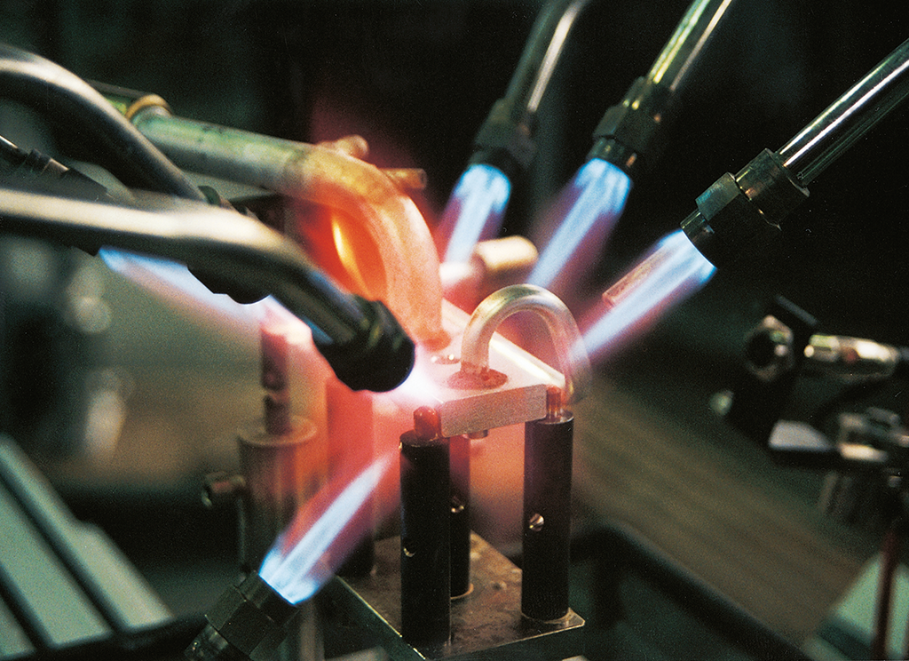
Thermal management of electric vehicles is faced with challenges, as batteries need to be kept at a defined temperature range between 15°C and 35°C in order to function at peak performance throughout the life of a vehicle. The manufacture of such battery cooling systems involves controlled atmosphere brazing technology using noncorrosive flux. OEMs develop different battery cooler designs that require adapted fluxing methods.
Thermal management of electric vehicles is faced with challenges, as batteries need to be kept at a defined temperature range between 15°C and 35°C in order to function at peak performance throughout the life of a vehicle. The manufacture of such battery cooling systems involves controlled atmosphere brazing technology using noncorrosive flux. OEMs develop different battery cooler designs that require adapted fluxing methods.
During recent years, gel blockage in engine coolant systems with aluminum heat exchangers produced by CAB has gotten more and more attention in the automotive industry. A general understanding of gel formation processes in engine coolants and the role that flux residues on internal surfaces of brazed heat exchangers may or may not have is of significant interest.
In everyday practice we can encounter problems connected with brazing imperfections – often manifested as leaking. In order to identify the failure root causes, usually a detailed examination needs to be perform. Optical metallography is one of the most important tools for such an analysis.
In everyday practice we can encounter problems connected with brazing imperfections – often manifested as leaking. In order to identify the failure root causes, usually a detailed examination needs to be perform. Optical metallography is one of the most important tools for such an analysis.
Procedure
This section describes the necessary steps and control procedures to ensure a properly brazed joint.
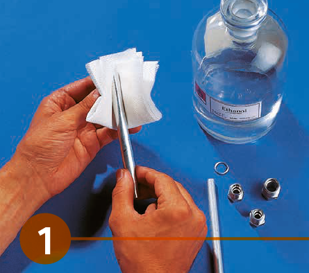
1. Clean the Components
The joint area must be cleaned free of cutting and machining lubricants. Aqueous cleaning, solvent dipping or wiping are acceptable procedures.
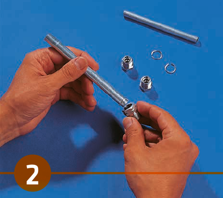
2. Assemble the Components
The components are assembled with the filler alloy ring in place. There must be intimate contact between the two components to be joined and the alloy ring.
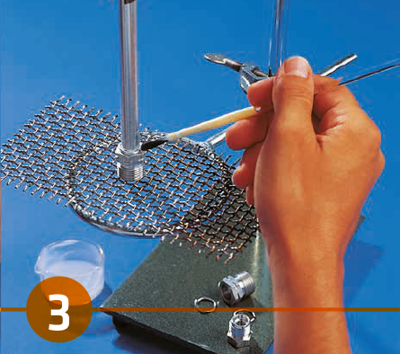
3. Apply the Flux
The flux is then applied with a small brush around the circumference of the joint at a loading of about 25 to 30 g/m2.
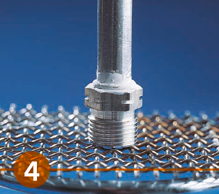
4. Dry the Flux
The flux should be allowed to dry before the application of intense heat to begin brazing. This can be done by allowing the joint to air dry or alternatively by gently heating the surrounding joint area with the flame, which will heat the metal and dry the flux. Intense heat should be avoided before the flux has dried, otherwise splattering and flux fall-off will occur.
5. Heating
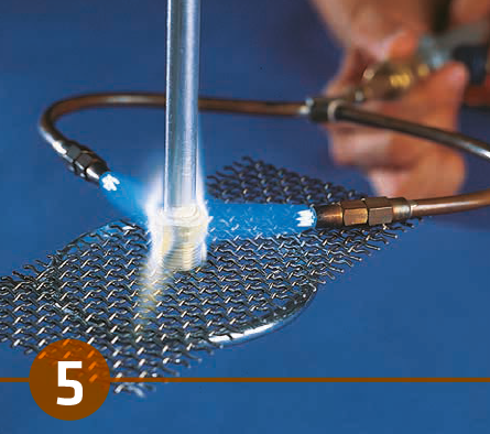
Once the flux has dried, more intense heat to begin the actual braze sequence can be applied. The braze flame should not be allowed to impinge on any one area very long to avoid overheating and burnthrough. The component with the higher thermal mass should be heated more. The flame should not be allowed to rest on the flux or preform ring to avoid premature melting before the joint area is uniformly heated to braze temperature. The flame should be kept moving at all times, moving back and forth between the components of different mass in such a way as to bring the entire joint to temperature uniformly.
There are three temperature indications in NOCOLOK ® flux flame brazing. The first is the appearance of a yellow flame at the Al surface. This indicates that the surface is starting to overheat/burn, since the aluminum skin always runs hotter than the component center.
The flame must visit the area less frequently to avoid burning. The second indicator is the first sign of flux melting, that is the fluxed area turns from white to clear. This indicates that the joint temperature is about 565 °C.
At this point the flames can be played directly on the joint and filler metal ring. Very shortly after flux melting, the filler metal ring begins to loose shape (third temperature indicator) and begins to melt at 577 °C. The molten filler metal is quickly drawn into the joint by capillary action. As soon as the full preform ring is molten, the flame should be quickly removed and the brazed joint allowed to cool.
6. Post Braze Treatment
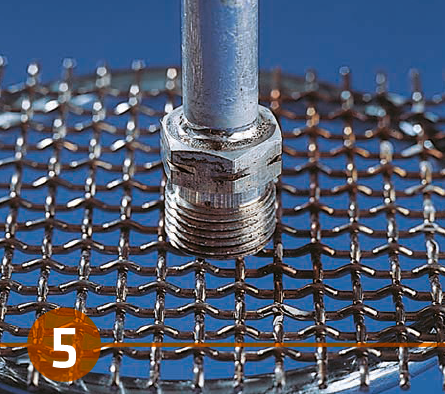
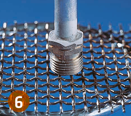
After cooling, no further treatment is required. The flux, although visible is non-hygroscopic and in standard applications non-corrosive. With the brazing conditions optimized, meaning minimal flux residue, the surfaces can be painted with relatively good paint adhesion over the flux residue.
If absolutely desired, the flux residue can be removed, but only by mechanical means such as wire brushing and grit blasting. Removing the flux residue is recommended only when joint cleanliness is absolutely imperative.
Recommended equipment for flame brazing
Since the principles of flame brazing can be explained using the most basic equipment, only the equipment necessary for manual flame brazing is described. From the basic principles, all other equipment is only a matter of the degree of automation the end user wishes to achieve.
Hardware
Torch
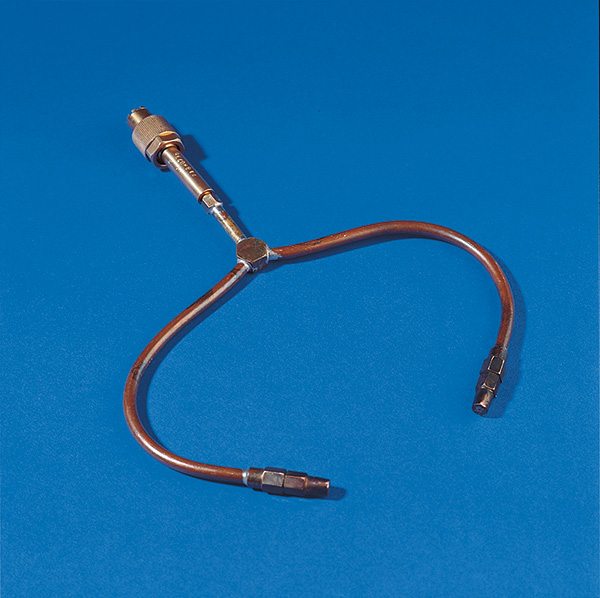
It is critical that the joint area is brought up to temperature uniformly. For this reason a dual headed torch capable of heating the joint from 2 sides is recommended.
Torch Tip
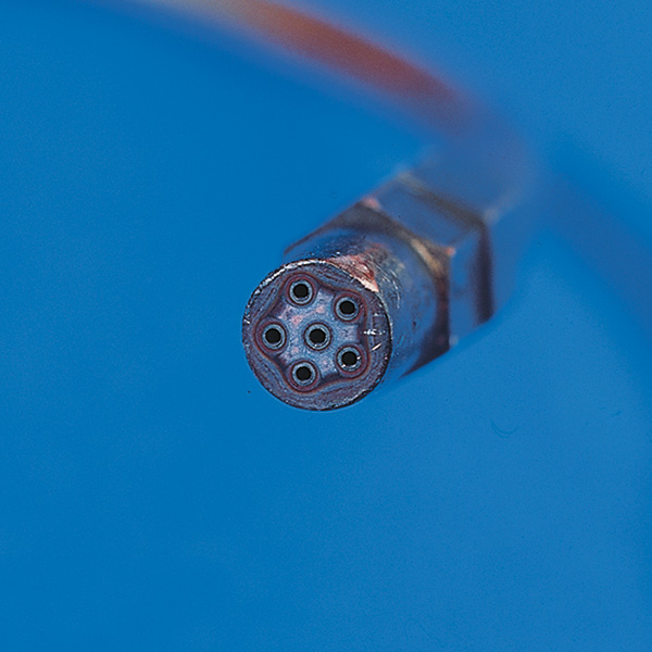
A multi-orifice tip generates a broader flame at the exit of the tip. This feature enhances component temperature uniformity during heat up. Pin-point flames should be avoided as burn-through can easily occur.
Consumables
Gas
Most commercial gas mixtures are acceptable for flame brazing Al:
- oxygen – propane
- oxygen – methane
- oxygen – natural gas
- oxygen – acetylene (oxyacetylene)
- Oxyacetylene combination produces the hottest flame and may be used, but with extreme care to avoid overheating and burn-through.
Filler Metal
The filler metal alloy most commonly used for flame brazing Al is AA4047 which contains 11 to 13 % Si. The Al-Si phase diagram shows the eutectic at 577 °C with 12.6 % Si. AA4047 filler alloy therefore has the lowest melting temperature with the highest fluidity, ideal properties for flame brazing Al.
The filler metal is available in a variety of shapes and forms including wire, rings, foil and powder. When used as a powder, it is usually mixed with flux and a carrier to form a paste (more on pastes below). The filler metal wire is also available commercially either cored or coated with flux, precluding the application of flux.

Brazing Paste
Commercially available brazing pastes consist of the flux, powdered filler metal and a binder/carrier to keep everything in uniform suspension. This paste is all inclusive, there is no need to supply flux or filler metal to the joint separately. Brazing pastes can also be applied with automatic dispensers, with syringes or by brush application.
Flux Paste
This is very similar to brazing pastes except that there is no powdered filler metal present, meaning that flux pastes requires filler metal in one form or another to be added to the joint separately. The advantage of using a flux paste is that the end user does not have to prepare his own paste.
In-House Paste Preparation
The least expensive and most common is the in-house preparation of flux pastes. The flux is mixed with either water or alcohol and/or water at 40 % to 60 % solids. Using some alcohol in the paste formulation allows for quicker drying. Using pastes prepared in-house of course requires that the filler metal be supplied to the joint separately.
These pastes are not easily dispensable automatically and are most often applied with a brush.
For brazing a tube-to-tube joint, the table below summarizes the complexity level in applying the flux and filler metal in their various forms:
| Flux Cored or Coated Wire | Brazing Pastes | Flux Pastes | In-House Paste Preparation |
| 1. Preplace ring at the joint | 1. Apply or dispense paste at the joint |
1. Preplace ring at the joint | 1. Prepare paste |
| 2. Braze | 2. Dry | 2. Apply or dispense paste at the joint |
2. Preplace ring at the joint |
| 3. Braze | 3. Dry | 3. Apply paste at the joint | |
| 4. Braze | 4. Dry | ||
| 5. Braze |
Go to Part 1
Go to Part 3
Go to Part 4
Go to Part 5
Flame brazing of aluminum is not new. In fact the very first brazed aluminum assemblies were produced using a chloride based flux and a flame as the heat source. What has changed over the years is the sophistication of the types of fluxes available and to a certain extent the alloy selection.
Introduction
However, even if one returns to the absolute basics of a flame, filler metal and flux, there remains a great deal to be learned about the fundamentals of flame brazing of aluminum. This becomes especially evident when the brazing engineer applies his techniques and equipment to NOCOLOK ® Flux flame brazing and years of learned practice seem to fail. This is largely due to the fact that the years of acquired knowledge of flame brazing aluminum has come from corrosive chloride-based flux brazing. Unfortunately, the same techniques can not be directly applied to NOCOLOK ® Flux flame brazing. It is therefore the intention of this article to re-familiarize the brazing engineer with the fundamentals of flame brazing aluminum and use those fundamentals to realize all the advantages of NOCOLOK ® Flux brazing.
What is Flame Brazing?
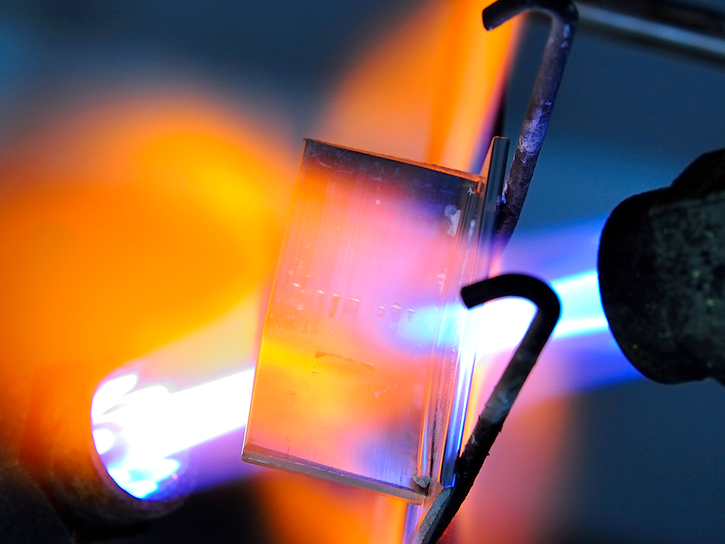
According to the American Welding Society, brazing is the joining of metals using a molten filler metal, which on cooling forms a joint. The filler metal melting temperature is above 450 °C, but below the melting point of the metals.
Flame brazing then implies the use of a flame as the heat source to accomplish what is described above.
Flame brazing lends itself well to joining components with simple configurations such as tube-to-tube, tube-to-fitting and joints having large thermal mass differences. Since much faster heating rates are possible than in furnace brazing, flame brazing is versatile and as will be explained in more detail later, can braze some Mg containing alloys.
What is NOCOLOK ® Flux?
NOCOLOK ® flux is a white powder consisting of a mixture of potassium fluroaluminate salts of the general formula K1-3 Al‑F4-6. The flux has a defined melting point range of 565 °C to 572 °C, below the melting point of the Al-Si brazing alloy. The flux is non-corrosive and non-hygroscopic and is only very slightly soluble in water (0.2 % to 0.4 %). The shelf and pot life of the flux is therefore indefinite. The flux does not react with Al at room temperature or at brazing temperature and only becomes reactive when molten.
Role of the Flux
Once molten the flux works by dissolving the oxide film on the Al surfaces to be joined and prevents further oxidation. The flux wets the Al surfaces and allows the filler metal to flow freely into the joints by capillary action. Upon cooling, the flux solidifies and remains on the surfaces as a thin, tightly adherent film, which need not be removed.
Joint Clearances
The recommended gap tolerances for flame brazing range from 0.1 mm to 0.15 mm. Larger gap clearances can be tolerated, but capillary action is reduced, gravity activity is increased and more filler metal may be required. Friction fits should also be avoided as this will restrict filler metal flow and result in discontinuities in the brazed joint area.
