Analysis of Brazing Imperfections by Metallographic Investigation / Optical Microscopy – Part 1
In everyday practice we can encounter problems connected with brazing imperfections – often manifested as leaking. In order to identify the failure root causes, usually a detailed examination needs to be perform. Optical metallography is one of the most important tools for such an analysis.
The purpose of this article is to present the basic principles for performing analysis of brazing joints, and to show what information can be obtained from the investigation.
Before starting to work with an optical microscope, the part to be examined must be prepared appropriately. There are several steps in this procedure:
- Cutting out smaller pieces to about 30mm to 40mm with a band saw
- Embedding the cut sections in epoxy resin
- Step grinding with sand paper (220 grit, 500 grit, 1000 grit)
- Polishing with diamond suspension (6 µm, and 3 µm) and with oxide polishing suspensions (OP-S)
- Microscopic observation in non-etched conditions – mainly to determine if the quality of polishing is sufficient
- Microscopic observation after etching – most common etchant: 0.5% hydrofluoric acid, (10 – 15 seconds immersion)
There are usually two steps in a metallographic examination.
The first one is to evaluate the brazing quality. It is usually performed when introducing a new product. In such case the manufacturer should define the way the sample is cut for microscope observations. In most cases the tube to header and the fin to tube joints are examined. Such exemplary cutting is shown in Fig. 1:
Fig. 1: Cutting of a radiator for examination of the joint quality
a) Brazed part with marked cutting lines
b) Part after cutting along line 1
c) Part after cutting along line 2
The second step is connected with the actual examination of the parts – looking for root causes of not brazed parts.
It is of primary importance to choose properly the observation plain. In most cases it runs across the examined defect. This will be seen case by case in the following industrial cases examples.
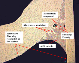
However; before we go into fault analysis we should understand what can be seen in an optical microscope metallographic picture. Figure 2 represents the metallurgical structure of a tube to header joint of a brazed aluminum radiator.
Fig. 2: Metallographic structure of a tube to header joint – etched with HF
Apart from the intrinsic features of the brazed structure quite often we can observe another phenomena strictly connected with the brazing process. Example of such phenomenon is shown in figure 3.
Fig 3: Examples of structural brazing phenomena
a) Silicon diffusion
b) Erosion
c) Liquid Film Migration
Silicon diffusion is a phenomenon where silicon diffuses from static liquid filler into the base metal and aluminum diffuses into the liquid filler – resulting in partial melting of the base metal at brazing temperature. The extent of this phenomenon is enhanced by too high brazing temperature and/or too long time at brazing temperature.
The phenomenon of diffusion sometimes can develop into so-called erosion. In such cases the liquid part of the base metal had flown away – leaving a gutter behind. That can potentially happen at the end of a brazing cycle, when significant temperature gradients develop during cooling. It should be noticed that this phenomenon, which results in thinning out of for example the tube wall cross section, is very dangerous for part performance, because the thinner tube wall could be a potential place for fatigue and/or corrosion failure.
The Liquid Film Migration [LFM] physically is an entirely different phenomenon than the two ones discussed above. During brazing, there are always some interactions between the filler alloy and the base alloy. They take place before and after melting of the filler alloy. However, in some situations they have a very specific character. It is a phenomenon of rapid silicon diffusion into the matrix alloy. It starts at temperatures below the brazing window. During that process a moving liquid interface is created, which sweeps from the clad/core interface into the core of the material.
The degree of LFM depends on cold deformation induced to the base metal before brazing and also strongly depends on the alloy type of the part. Since this process diminishes the amount of liquid available to form joints – and it can also destroy a sacrificial layer in the base alloy (e.g. used for corrosion protection) – it should be avoided in the brazing practice. It is worthwhile pointing out that minimization of LFM can be achieved by proper choice of the base material and its temper, thus for a given part it must be done at designing stage.


Hinterlasse einen Kommentar
An der Diskussion beteiligen?Hinterlasse uns deinen Kommentar!