Analysis of Brazing Imperfections by Metallographic Investigation / Optical Microscopy – Part 2
In everyday practice we can encounter problems connected with brazing imperfections – often manifested as leaking. In order to identify the failure root causes, usually a detailed examination needs to be perform. Optical metallography is one of the most important tools for such an analysis.
The purpose of this article is to present the basic principles for performing analysis of brazing joints, and to show what information can be obtained from the investigation.
Go to part 1
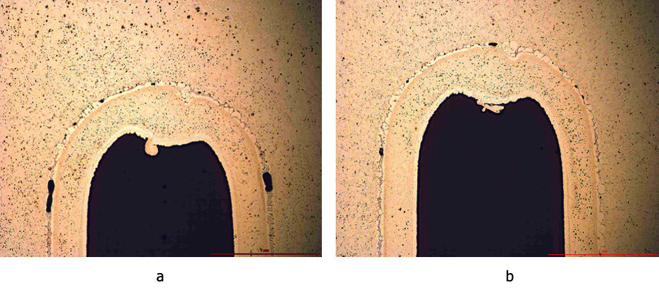
The major fault in any brazed joint is porosity – or using other words: presence of voids. Their sizes can vary substantially from very small ones to much bigger ones. The fact is that for the CAB process there is no numerical criterion for determining the level of acceptable porosity. Case by case criteria are used for accepting the quality of joints, though the obvious standard is the so called leak test – to check if the part is tight.
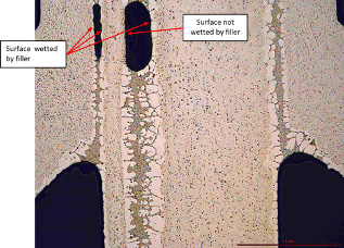
When porosity is too large it can develop into a leak. Thus, identification of its origin is of great importance. As a first step it must be identified if the free surface of the porosity was wetted by the filler alloy. That can be determined by presence or absence of residual filler alloy clad layer on the joint surface. It is manifested by the presence of a white ribbon at the surface of porosity (see Fig. 5).
Fig. 4: Examples of brazed joints with porosity
a) Poor quality joint
b) Good joint quality, with only tiny porosity
Fig. 5: Large porosities showing evidence of filler alloy wetting and lack of wetting
The joint surface might be not wetted by filler – because of: contamination, too large gap, insufficient volume of the liquid. Only after determining the cause of porosity we can undertake proper counter measures going in a right direction.
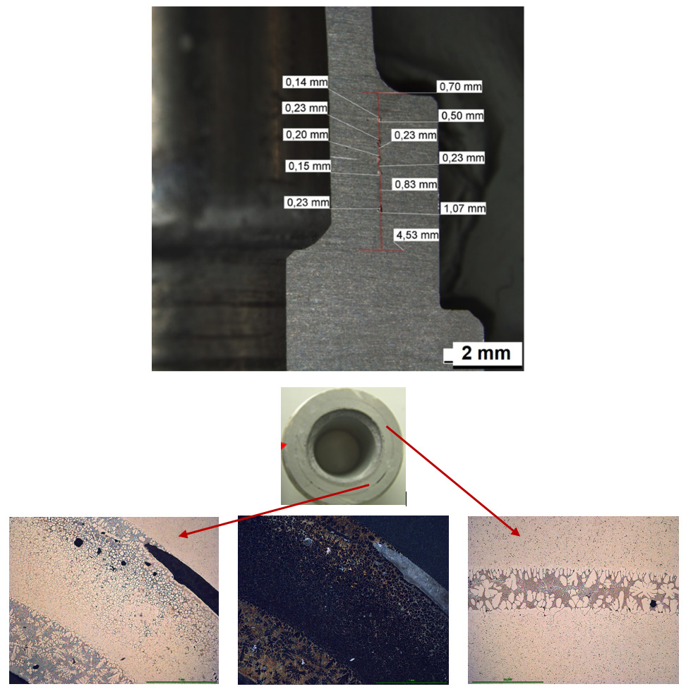
Approaches to porosity problems will be different when looking at flame brazing – dealing with a single or just few connections. Most of the OEM’s specify the percentage of maximum porosity volume and its maximum size; for example: the brazing depth must be larger than 5 mm with 2.5 mm length of the joint pore free and 60% of the total length free of voids. In such a case accurate measurements of the joint porosity must be performed. This it is a destructive method, assuming that the porosity in other parts is at a similar level.
Left: Partial melting of the base alloy Middle: Dark field image Right: Good quality joint
Fig. 6: Example of brazing with area of overheated joint.
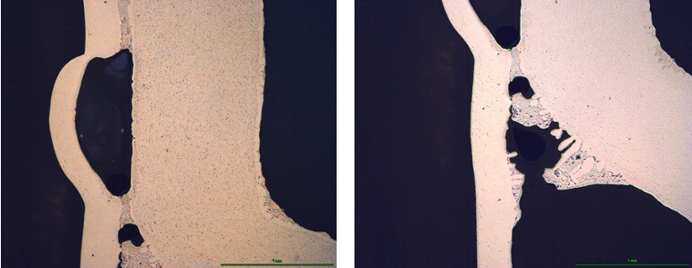
Fig. 7: Field return leak due to a bulge in the joint
In another case a field return leaking radiator is presented. A bulge was observed that broke open next to the tube to header joint. It was assumed that during service moisture got into originally closed voids and then the water going through a cycle of freezing caused the voids to bulge up – leading eventually to a leak. However, there was a question why there were discontinuities in the originally isolated joint. Optical metallography revealed evidence of corrosion, which enabled moisture to penetrate into the prior isolated void.
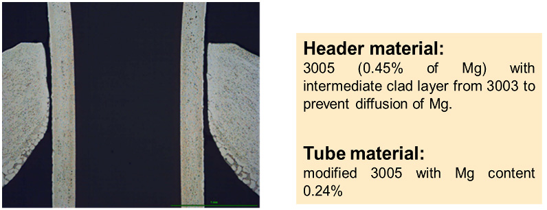
Fig. 8: Joint defect due to the presence of magnesium in the base alloy
In the above case (Fig. 8), an intermediate clad layer made of 3003 alloy was supposed to stop diffusion of Mg to the surface of the header (multi-clad layer brazing sheet) – thus eliminating the negative influence of Mg on flux action. But inside the header opening – simply due to the cutting of the material – this protection was removed, and Mg could diffuse into the joint – causing flux poisoning, which resulted in lack of joint. Such situation can be considered as a design mistake. It can be fixed only by changing the material of the header.
To summarize the above:
- Optical metallography is a powerful tool for investigating imperfections in brazing.
- Sample preparation – i.e. proper choice of observation plane and perfect polishing – is a prerequisite for a thorough analysis of the brazing failures.
- Optical metallography allows for determination of the braze quality by assessing voids and other brazing faults.
It also allows to identify the root causes of the examined faults, thus enabling introduction of proper corrective actions.

Hinterlasse einen Kommentar
An der Diskussion beteiligen?Hinterlasse uns deinen Kommentar!