Schlagwortarchiv für: Brazed Microchannel

Technical Information by Daniel Lauzon

Manufacturing Processes

By the early nineties, aluminum had already almost completely replaced copper/brass in radiators at the Ford Motor Company. Ford had gone through mass production of mechanically assembled radiators starting in 1982 and introduced vacuum brazing in 1983. In 1989, Winterbottom reported,

…”the manufacturing capability and the superior corrosion resistance of aluminum was well established, and the competition between copper/brass and aluminum in the radiator application essentially ended.” (5)

By the mid-nineties, vacuum brazing was becoming less popular due to its high maintenance furnaces and less forgiving nature. Vacuum brazing was giving way to the more popular noncorrosive flux brazing process, also known as Controlled Atmosphere Brazing or CAB. Today, CAB brazing is the preferred process for manufacturing automotive heat exchangers worldwide. In Solvay’s estimate, there are now more than 600 CAB brazing furnaces in the world with more than 100 more in plan.

No discussion on the differences between copper/brass and aluminum radiator manufacturing processes would be complete without bringing up the topic of CuproBraze®. It is a new process for manufacturing copper/brass radiators developed by the International Copper Association (ICA) in conjunction with Outokumpu Copper Strip AB of Sweden (6). This process was surely developed to combat copper’s decline in the automotive heat exchanger markets and does appear to offer many advantages over the traditional copper/brass “soft-soldering” technology. But alas, no in-roads have been made in passenger vehicle radiators and the new technology is has found a niche in some truck and off-road vehicle markets.

Environmental and Recyclability Considerations

From an environmental perspective, there are no special considerations for adopting the noncorrosive flux brazing process. Unlike conventional Cu/brass radiator technology, there are no heavy metals employed in any part of the process, including the flux, lubricants, cleaning solutions and alloys. The wastewater stream contains some fluorides and the exhaust effluent from the furnace must be scrubbed due to the low level (ppm level) formation of HF gas, but these have not prevented the worldwide successful commercialization of the technology.

There are also no major recycling issues with aluminum radiators. The filler metal or ‘solder’ used in aluminum heat exchanger manufacturing is, after all, just another aluminum alloy. The common alloying elements such as silicon in the filler metal do not pose any issues and brazed aluminum heat exchangers are recyclable for use in the secondary aluminum industry (e.g., castings) or at the very least as high-value scrap.

Performance and Reliability

There are very few references in the literature showing side by side comparisons of reliability and performance characteristics of Cu/brass and aluminum heat exchangers for the automotive industry. Years ago, Calsonic introduced aluminum radiators to the agricultural machinery market in Japan and did publish some side by side reliability data (7). Calsonic’s comparison study included corrosion testing, pressure cycling, vibration testing and cooling system performance. The results showed a 30 percent reduction in weight compared to conventional copper radiators and better performance in actual use conditions.

Other Applications

Non-corrosive flux brazing of aluminum is used primarily for automotive heat exchanger manufacturing. However, there are several other small markets where non-corrosive flux brazing is used:

  • In the manufacturing of small household appliances where the aluminum heating elements for coffee makers, electric tea kettles, clothes dryers and clothes irons are brazed to a substrate.
  • In the manufacturing of high-end pots and pans where the stainless steel pot/pan is brazed to an aluminum base plate.
  • In refrigerators where copper or aluminum tubing is brazed to aluminum roll-bond panels.
  • In heat sinks for electronics

Future Developments

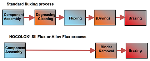
It is this author’s opinion, based on more than 30 years experience in the automotive heat exchanger industry that aluminum is here to stay. There is no indication from the passenger vehicle OEM market that copper/brass will make a comeback. On the materials side, the aluminum suppliers will continue to look for ways to improve strength and corrosion resistance to down-gauge even further. On the manufacturing side, there is no sign that flux usage will disappear. What is foreseen is a more efficient use of flux in terms of selective deposition – prefluxing of select components using binders – in order to minimize waste and flux consumption. In 1995 when one spoke of non-corrosive type fluxes, there was really one type of flux chemistry available. Today, several types of fluxes are available, from fluxes capable of tackling higher magnesium contents, to fluxes capable of generating sacrificial corrosion layers in-situ. There are fluxes capable of generating filler metal in-situ and there are fluxes dedicated for electrostatic fluxing equipment and so on. There are also continuous improvements made to controlled atmosphere brazing furnaces for aluminum to improve efficiency and throughput. We will continue to see aluminum radiators made cheaper, smaller and stronger.


References:

  1. Gray, Alan., The Growth of Aluminium in Automotive Heat Exchangers, 3rd International Congress – Aluminium Brazing, Düsseldorf, 2004.
  2. Ross, Gary R, Curtindale, William D, Controlled Atmosphere Brazing of Roll-formed Folded Aluminum Heat Exchanger Tubes, Therm Alliance International Invitational Aluminum Brazing Seminar, 1999.
  3. Jackson, A., Price H.C.R., High Performance Core Technology for Brazed Automotive Radiators, VTMS C496 / 076, 1995.
  4. Scott, Arthur C., Corrosion Performance of Long-Life Automobile Radiators, VTMS3, 971857, 1997.
  5. Winterbottom, Walter L., The aluminum auto radiator comes of age, Advanced Material and Processes, pp 55-56, Vol. 5, 1990.
  6. www.cuprobraze.com
  7. Ochiai, H., Hataura, K., Application of Non-Corrosive Flux Brazing Aluminum Radiator to Agricultural Machinery, SAE Conference paper 911298, 1991.

Technical Information by Daniel Lauzon

Synopsis

The use of aluminum alloys in automotive heat exchanger applications has steadily increased over the nearly 3 decades, particularly in engine cooling and air conditioning systems for passenger vehicles. This paper will briefly review what precipitated the transition from traditional copper/brass to aluminum radiators by outlining the technical merits such as weight savings, performance, corrosion resistance and manufacturing processes.

Introduction

In the early eighties, copper/brass enjoyed approximately 95% of the radiator market in North America. Since the mid-eighties, the aluminum content of passenger vehicles has nearly doubled in order to satisfy environmental considerations such as reducing emissions and improving fuel efficiency through weight savings. By the end of 2005, it is expected that at the OEM level, roughly 100% of passenger car radiators, heater cores, condensers and evaporators will be manufactured from aluminum (1).

Weight Savings

It is common knowledge that copper has superior thermal conductivity than aluminum. And it is also known that aluminum is about one third the density of copper (2.7 g/cm³ for Al and 8.9 g/cm³ for Cu). One might conclude then that you use copper/brass when you want heat transfer efficiency (good cooling) and use aluminum when you want weight savings. However, as will be explained in more detail in the section below, aluminum radiators can be significantly lighter than similar copper/brass units and still provide better cooling.

Performance

The performance characteristics of a radiator must take into consideration more than just the thermal conductivity properties of the metal. The radiator tubes transfer heat from the coolant to the fins. Air passing through the fins carries heat away. It stands to reason then that the more contact area between the fins and tubes, the more efficient the radiator will be at dissipating heat. Figure 1 (bottom) shows a typical cross-section for a 4 row copper/brass radiator. Area “A” is where maximum heat transfer occurs, i.e., where the fins make contact with the tube. Area “B” on the other hand is considered dead-space, where no heat transfer takes place.

Figure 1: Fin-to-Tube Contact Area in Aluminum and Copper/Brass Radiators

Figure 1: Fin-to-Tube Contact Area in Aluminum and Copper/Brass Radiators

Therefore, better heat transfer efficiency would result if the tubes were wider, thereby increasing the fin-to-tube contact area as shown at the top of Figure 1. A typical copper radiator uses 3/8” to 5/8” wide tubes. However, increasing the width of the tubes would also require an increase in tube wall thickness to prevent ballooning and for copper, the penalty in weight gain could be severe. Increasing the tube wall width to 1” would require double the wall thickness of 5/8” tube resulting in a radiator weighing up to 60 lbs.

The answer to the above dilemma is to use aluminum. Using the example in Figure 1, a radiator could be manufactured with 1” to 1 ¼ “ wide tubes with a suitable wall thickness to prevent ballooning and still be up to 60% lighter than the same radiator built from copper. Furthermore, the increased tube-to-fin contact area in this example increases cooling capacity by roughly 25%.

The ability to use wider tubes also means that one can achieve the same cooling capacity in a one-row aluminum design compared to a multi-row copper/brass design. Single row radiator cores also have a huge advantage in being able to reduce air-side pressure drop as a result of much less resistance to air flow through the thickness of the core. The limitations in copper/brass multi-row designs combined with advantages of improved heat transfer from wide-tube, singlerow designs have focused the industry’s attention to improving the single row aluminum heat exchanger. The industry’s attention thus turned to increasing the fin-to-tube contact area by widening the tubes even more, thereby maximizing the heat transfer efficiency of a single row core.

This led to the development of the rolled formed aluminum tube or “B-tube”. This manufacturing process adds a mid-section supporting member (see Figure 2) which effectively reduces the major axis tube width by 50%. This allows the width of the tube to increase without the need to increase the tube wall thickness. The details of radiator B-tubes is beyond the scope of this article and are discussed elsewhere (2, 3)

Figure 2: Generic Configuration of a Radiator Folded “B-tube”

Alloy Developments – Strength and Corrosion Resistance

Radiators and condensers face the most corrosive environment of all the automotive heat exchangers. Sea salt from coastal regions, acid rain in industrial cities, road salts in regions with snow and ice all contribute to fin and tube corrosion. In the early eighties when aluminum was just making its mark on the heat exchanger industry, there was a legitimate concern over corrosion resistance (4). At the same time, even with the switch to lighter weight aluminum, there was still a drive toward down-gauging for cost and weight savings. While standard aluminum alloys such as AA3003 are still used widely in the heat exchanger industry today, the result has been a push towards higher strength, higher corrosion resistance alloys for more than two decades.

The requirement for the ‘ten year’ radiator was soon met with a variety of alloy developments and sacrificial corrosion protection schemes. In fact, so great was the push for newer, stronger and more corrosion resistant alloys (too numerous to mention here) that tube wall and finstock thicknesses down-gauged from 0.020” and 0.008” in 1985, to as low as 0.010” and 0.002”, respectively, in 2004 (1). It is difficult to imagine even more down-gauging beyond the current 0.010” and 0.002” for tube and finstock respectively, but the trend is still evident. It is even more difficult to imagine similar trends with copper/brass in the same timeframe!


References:

  1. Gray, Alan., The Growth of Aluminium in Automotive Heat Exchangers, 3rd International Congress – Aluminium Brazing, Düsseldorf, 2004.
  2. Ross, Gary R, Curtindale, William D, Controlled Atmosphere Brazing of Roll-formed Folded Aluminum Heat Exchanger Tubes, Therm Alliance International Invitational Aluminum Brazing Seminar, 1999.
  3. Jackson, A., Price H.C.R., High Performance Core Technology for Brazed Automotive Radiators, VTMS C496 / 076, 1995.
  4. Scott, Arthur C., Corrosion Performance of Long-Life Automobile Radiators, VTMS3, 971857, 1997.
  5. Winterbottom, Walter L., The aluminum auto radiator comes of age, Advanced Material and Processes, pp 55-56, Vol. 5, 1990.
  6. www.cuprobraze.com
  7. Ochiai, H., Hataura, K., Application of Non-Corrosive Flux Brazing Aluminum Radiator to Agricultural Machinery, SAE Conference paper 911298, 1991.

Summary

The article was written on the basis of frequently asked questions from companies which either wanted to start a new all-aluminium brazing production of heat exchangers or wanted to convert from copper and aluminium mechanical assembly design to all-aluminium brazed parts. The questions were grouped into three main categories: Equipment (emphasis on assembling process), Process (emphasis on different fluxes and fluxing methods) and Corrosion.

Specific production challenges are also presented, which are important not only to newcomers of all-aluminium brazed heat exchangers, but to established companies as well. These include typical brazing problems such as managing leaks and the basics of brazing copper to aluminium. These topics are discussed by their relevance to the brazing parameters and their role in successful brazing.

Content:

  1. Introduction (Part 1, issue July 2013)
  2. Equipment (Part 1, issue July 2013)
  3. Brazing process (Part 2, issue August 2013)
  4. Brazing copper to aluminium (in this issue)
  5. Corrosion resistance (in this issue)
  6. Summary (in this issue)

4. Brazing copper to aluminium

When replacing a heat exchanger in an existing design, very often the connecting pipes are made from copper. Therefore the typical question: ”Is it possible to braze aluminium pipe to a copper one?” The answer is: Yes, it is possible by flame brazing. At 548°C there is the formation of a eutectic between copper and aluminium. This reaction is very rapid; therefore accurate temperature control and short process times such as with flame brazing are required. It is easier to braze at a temperature below the eutectic formation, thus lower melting point filler alloy and flux are required. In this case the recommended filler alloy would be ZnAl and Cs-Al-F flux. When copper remains in contact with aluminium for a longer period of time, such as in furnace brazing, an intensive dissolution of aluminium is observed. Therefore, for any factory which has production of copper and aluminium brazed exchangers, it is of very high importance to keep those two activities well separated from each other. A result of contamination of a condenser tube with a small chip of copper is shown in fig 7.

Fig. 7: Hole in a brazed tube surface burned through by a copper chip

Fig. 7: Hole in a brazed tube surface burned through by a copper chip

When joining copper to aluminium it must be remembered that extreme galvanic corrosion can take place when the joint is exposed to a humid or wet environment. It is therefore obligatory to make sure that Cu-Al joints are not exposed to water during service. This can be achieved for example by using temperature shrinking plastic sleeves over the tube joint.

5. Corrosion resistance

Corrosion resistance of condensers for air conditioning system is one of the major utility properties. Thus the first question: ”Is there any approved test for determining the corrosion resistance requirements for HVAC heat exchangers?” Unfortunately the HVAC industry has not yet developed a commonly accepted test standard for assessing corrosion resistance. In the automotive world, the most common tests used by manufacturers are:

  • SWAAT (ASTM G85 annex A3) – seawater acidified test, cyclic; it is an aggressive corrosion test commonly used in the automotive industry, but the characteristic of the test does not correspond well to the working conditions of stationary units.
  • Salt Spray Test (ASTM-B-117, ISO 9227), it is a test better reflecting the working conditions of stationary units, but it is not sufficiently aggressive (too long time for completion).

Other methods developed in response to observed corrosion due to rain or condensation water remaining on the units for a prolonged time, is the socalled soaking or water-exposure test. In this experiment a small cut-out heat exchanger section is immersed in demineralized water for a certain period of time and the concentration of ions in the water after soaking is analyzed. The procedure has not been standardized, therefore it is not really possible to compare results obtained by different companies, but the test can be used for direct comparison of different fluxes and materials. For now no correlation between its results and real life time has been established.

Invariably many companies when considering production of brazed aluminium heat exchange ask a question: ”What sort of alloys should be chosen for the best corrosion performance?” This topic is quite complex and there is no single “best answer”. In the authors’ opinion the best method is to discuss the subject with the aluminium suppliers who have a lot of knowledge and experience in choosing the optimal aluminium alloys. Every heat exchanger is an assembly of different components and when considering its corrosion resistance, the alloys of individual elements should be looked at as a unit in which mutual interactions between each component are taking place.

There are many different working environments which will significantly influence the corrosion behaviour of the parts. According to [8] the following major types can be distinguished:

Coastal/Marine:
This environment is characterized by an abundance of sodium chloride and sulphur compounds carried by spray, fog or winds.

Industrial:
This environment can be much diversified, where sulphur and nitrogen contaminants are most notable.. Many of the gases emitted during different combustion processes come back to the ground in form of acid rain. Also this environment produces a lot of different small particles in the form of dust which covers the equipment creating potential increased corrosion hazards.

Combination Marine/Industrial:
A combination of the above two factor create the harshest environment for any HVAC equipment.

Urban:
This environment is characterized by high level of automobile and house heating emissions. These are mainly SO2 and NOx compounds resulting also in acid rains.

Rural:
Usually these are unpolluted areas; however in some cases pollution may appear with higher a concentration of ammonia and nitrogen originating from animal excrement and fertilizer use.

The best solution would be to choose the alloys according to the different working environments; this however has hardly ever been possible.

As a mater of fact, [8] suggests that in particularly aggressive environment the coils should always have additional protection layer/coating.

6. Summary

Thanks to technical advantages of brazed heat exchangers over the mechanical ones and driven by high copper prices, it seems that a change into all aluminium heat exchangers in the HVAC&R industry is inevitable. Though the process of conversion from copper and /or mechanically assembled heat exchangers is in most cases a significant challenge, when properly planned it can be done smoothly without any unpredictable surprises. The major aspects which should be considered are equipment choices with a special emphasis on the assembly method, selection of proper alloys and the most optimal fluxing technology. The required data for the project and investment decisions can be obtained by direct contacts with equipment and consumables manufacturers.


References:

8. Selection Guide: Environmental Corrosion Protec-tion, Carrier Corporation, Syracuse, New York, July 2009

Summary

The article was written on the basis of frequently asked questions from companies which either wanted to start a new all-aluminium brazing production of heat exchangers or wanted to convert from copper and aluminium mechanical assembly design to all-aluminium brazed parts. The questions were grouped into three main categories: Equipment (emphasis on assembling process), Process (emphasis on different fluxes and fluxing methods) and Corrosion.

Specific production challenges are also presented, which are important not only to newcomers of all-aluminium brazed heat exchangers, but to established companies as well. These include typical brazing problems such as managing leaks and the basics of brazing copper to aluminium. These topics are discussed by their relevance to the brazing parameters and their role in successful brazing.

Content:

  1. Introduction (Part 1, issue July 2013)
  2. Equipment (Part 1, issue July 2013)
  3. Brazing process (in this issue)
  4. Brazing copper to aluminium (in September issue)
  5. Corrosion resistance (in September issue)
  6. Summary (in September issue)

3. Brazing Process

Brazing parameters

Success or failure of any controlled atmosphere brazing process is always connected with brazing parameters. These are:

Temperature: The brazed part should achieve a surface temperature between 590°C and 605°C and remain at that temperature range between 2 to 3.5 minutes. The temperature must be measured by thermocouples placed directly on the brazed parts. To obtain the above condition the furnace temperature controls must be set according to the size of the part. The usual maximum set value is in the range of 620°C. Note that the furnace set temperature will always be higher than the maximum temperature reached on the component.

Flux load and uniformity: The goal of fluxing is to achieve uniform flux coating with a load between 3 and 5 g/m2. For more difficult joints, for example tube to header joints, slightly higher flux loads are often used.

There are two major methods for fluxing: by spraying flux water suspension all over the assembled part and electrostatic fluxing where the dry powder is sprayed over the part in a process similar to powder painting. These methods are described in detail in [4]. Recently precoating with pure flux or mixtures which produce filler alloy as well, has become increasingly popular. Precoating with NOCOLOK® Sil Flux in particular is often used for air conditioning condensers and evaporators (MPE designs). Properties and challenges connected with this technology are described in [5]. The choice of fluxing method has big impact on the process machinery. The fact is that any of the above methods when properly conducted secure the required flux load and its uniformity. Therefore the decision about the fluxing choice should be based on a cost calculation. The calculation needs to take into account the following categories: media, maintenance, environment (cost of waste utilization), raw materials and consumables, labour and investment costs (depreciation). The result is always a function of local factors and conditions.

Fig. 3: Production steps for brazing line with standard wet fluxing and for NOCOLOK® Sil Flux

Fig. 3: Production steps for brazing line with standard wet fluxing and for NOCOLOK® Sil Flux

Furnace atmosphere: The brazing furnaces are delivered with various systems on nitrogen feeding nozzles. Therefore one of the most important questions is: ”What is the principle for setting the nitrogen flow through the brazing furnace?” This is shown in fig. 4.

Fig. 4: Schematic of continues brazing furnace with recommended nitrogen flow balance

Fig. 4: Schematic of continues brazing furnace with recommended nitrogen flow balance

Joint geometry: By joint geometry one should understand the gap size between the elements to be joined and also the shape of the joint. The gap size for at least one component clad with filler alloy should be no larger than 0.15 mm and it should be remembered that along the joint there must be at least one point of intimate contact between the joint elements. The shape of the joints should be designed in such a way that there are no preferential paths for the filler alloy to flow. This concept called “competing joints” is explained in details in [6].

Filler alloy availability: This parameter is best expressed by the question: ”How much of the clad alloy actually forms the joint?” It is a common belief that there is as much filler metal available as clad material is rolled on the base metal. This, however, is never the case! During the heating cycle there is always some diffusion of silicon from the filler alloy into the matrix which diminishes the overall volume of liquid formed at brazing temperature. Sometimes even with a thick clad layer, only a fraction of the filler volume flows to form joints. Such an extreme limitation of the available liquid filler metal is connected with a phenomenon called “Liquid Film Migration [LFM]”. It is a phenomenon of very rapid diffusion of silicon into the matrix alloy. It starts at temperatures below the brazing window. This creates a moving liquid interface, which sweeps from the clad/ core interface into the core of the material. In this way the volume of available clad is diminished – thus making filling the larger gaps much more difficult. The degree of LFM correlates with cold work induced to the base metal before brazing through forming, bending and stamping and also strongly depends on the alloy type of the part [7].

Fig. 5: Localized LFM on a manifold clad surface

Fig. 5: Localized LFM on a manifold clad surface

Cleanliness: A question often raised about cleanliness is: ”How do we determine if a part is clean enough for successful brazing?” The fact is that cleanliness is a parameter for which there is no practical quantitative measure. Therefore, it is rather controlled by experience and the so called “good industrial practice”. Quite often an examination of the parts either before or after brazing is not sufficient to determine that the parts were not clean enough. Optical microscopy of the brazed joint or an investigation by Scanning Electron Microscope, in most cases determines if the root cause of the failure was connected with cleanliness. Sometimes insufficient degreasing or binder removal can be the reason for lack of braze (see fig. 6).

Fig. 6: Lack of braze due to insufficient cleanliness of one of the joint surfaces

Fig. 6: Lack of braze due to insufficient cleanliness of one of the joint surfaces


References:

4. Hans W. Swidersky, “Aluminium Brazing with Non-Corrosive Fluxes – State of the Art and Trends in NO-COLOK® Flux Technology”, 6th International Confer-ence on Brazing, High Temperature Brazing and Dif-fusion Bonding (LÖT 2001), Aachen, Germany (May 2001)

5. Leszek Orman, Hans W. Swidersky, ”Interaction of NOCOLOK® Sil Flux with Aluminum Base Alloy at Various Conditions”, AFC- Holcroft 12th International Invitational Aluminum Brazing Seminar 2007

6. Ralph Woods “CAB Brazing Metallurgy”, AFC- Holcroft 12th International Invitational Aluminum Brazing Seminar 2007

7. Aad Wittebrood, “Microstructural Changes in Brazing Sheet due to Solid-Liquid Interaction” Corus Technology B. V., ISBN: 978-90-805661-6-3

Will be continued…

Summary

The article was written on the basis of frequently asked questions from companies which either wanted to start a new all-aluminium brazing production of heat exchangers or wanted to convert from copper and aluminium mechanical assembly design to all-aluminium brazed parts. The questions were grouped into three main categories: Equipment (emphasis on assembling process), Process (emphasis on different fluxes and fluxing methods) and Corrosion.

Specific production challenges are also presented, which are important not only to newcomers of all-aluminium brazed heat exchangers, but to established companies as well. These include typical brazing problems such as managing leaks and the basics of brazing copper to aluminium. These topics are discussed by their relevance to the brazing parameters and their role in successful brazing.

Content:

  1. Introduction (in this issue)
  2. Equipment (in this issue)
  3. Brazing process (in August issue)
  4. Brazing copper to aluminium (in September issue)
  5. Corrosion resistance (in September issue)
  6. Summary (in September issue)

1. Introduction

Brazing Furnace

Increasing environmental concern has identified the air conditioning and refrigeration industry as one of the contributors to the greenhouse effect and ozone depletion.

Accordingly to [1] 15% of all electricity consumption in the developed world is used by the air conditioning and refrigerator industry. Increasing the efficiency of these heat transfer systems has the positive impact of decreasing electricity consumption and therefore the overall emission of CO2. The advantages of all aluminium brazed condensers in an air conditioning system are well described in [2]. For example one such case study [3] allowed for saving about 2700 USD during 6 months. The above advantages are currently well recognized by both the air conditioning manufacturers and their end users. It is our observation that the majority of the companies in the HVAC industry which have started or are about to start production of aluminium brazed heat exchangers have only limited experience with aluminium brazing; therefore providing them with maximum possible technical assistance from the supplier side is of high importance.

This article was written on the basis of our contacts with such companies having an aim to offer some assistance to all newcomers and companies facing some troubles with their new type of production.

2. Equipment

In most cases, the first question from a company that wants to start a new aluminium brazing activity is: “What kind of furnace should I buy?”

It is a complex issue which mainly depends on size of the products, its diversity and overall planned production volume. The general principles for the choice of the brazing furnace are shown in Fig. 1. It should be pointed out that the furnace manufacturers will make a brazing furnace customized to particular requirements of a given client.

Fig. 1: Basic principles for brazing furnace choice

Fig. 1: Basic principles for brazing furnace choice

Assembling units

In many cases the companies which are starting production of all aluminium brazed heat exchangers have been producing copper brazed heat exchangers. Therefore the natural question is: ”Can I use the same equipment which is used for copper units?”

The straight forward answer is: No! Aluminium requires high precision for assembling (recommended gap size is 0.1 to 0.15mm), which is hardly ever achieved for brazing copper parts. Also one should remember that any copper contamination on aluminium can cause catastrophic brazing failures (holes).

The process of component assembly can be done on a simple manual stacker or on machines with varying degrees of automation through to fully automated units. The level of automation should be mainly determined by the planned production volume, but also other factors such as local labour costs should also be considered.

Basic requirements for a manual assembling unit:

  1. Cores must be assembled on a perfectly flat heavy steel plate
  2. After laying out the tubes and fins, the tubes must be pushed precisely into position determined by the slots in the headers.
  3. To secure the above requirement:
    1. movement of the pusher must be allowed only in one direction (no side or up movement),
    2. travel distance must be accurately controlled – e.g. by mechanical block on the pusher,
    3. it is useful to have a special distances between tubes to secure the right spacing for each header slot,
    4. the vertical alignment of the tubes must be secured either by steel plate or by hammering the tubes with a special pad.
  4. Threading the headers on the tubes should be done in one single action which does not allow for any side or vertical deflection of the headers.
  5. After threading the headers the fixtures should be assembled and the tube pusher released.

The process of the part assembly is invariably connected with fixtures; these are the steel elements which hold the parts together during brazing and then removed after brazing. The most frequently asked question is: ”What should be the design of the brazing frames/fixtures?”

Basically there are rigid and elastic designs which allow for some expansion when the core is heated. For larger cores elastic design is preferred. This type of fixture is reusable, also known as a permanent fixture and can go through the brazing cycle several hundred times. Apart from that we could use single usage fixtures, known as disposable fixtures and these include steel wire and steel bands. The multi-use fixtures must be made of stainless steel and in most cases the single use fixtures are usually made of ordinary low carbon steel.

Fig. 2: Example of rigid and elastic fixtures

Fig. 2: Example of rigid and elastic fixtures

When designing the length of the fixture (distance marked in red as Ls in fig. 2, one must remember thatthere is a difference in thermal expansion coefficient between aluminium and steel. To compensate for this, the following assumption is made: The length of the steel fixture at brazing temperature must be equal to the nominal width of the aluminium exchanger at brazing temperature. On this basis, an equation can be used describing the linear change of dimensions with temperature.

Ls(1 + αstΔt) = Lo(1 + αalΔt)

Where:
Ls – length of steel fixture,
αst – thermal expansion coefficient for the fixture material,
αal – thermal expansion coefficient for aluminium,
Δt – Increase of the part temperature during brazing,
Lo – Nominal width of the part.

As an example, for a part having width of 900 mm and nominal tube spacing of 8 mm, solving this equation and taking into account the fact that after assembly there must be some pressure exerted by the fixture on the part, the length of the fixture should be 907.5 mm and the fin height 8.08 mm. The longer steel fixture is compensated by the increased fin height. It also means that after assembly the part will have a slightly barrel-like shape (bowed out at the sides).

The question: ”What final checks are required for brazed parts?”is also connected to equipment purchases. All brazed parts must be checked for leak tightness. The most simple method is the so called “under water test”. In this case the part is pressurized with air and lowered into a water bath to look for bubbles. However some end users require more accurate and reliable methods. In the automotive industry it is common to check condensers for leaks with high pressure and extremely sensitive helium leak detection devices.

Each product should be accepted by the end user. In every case the scope of acceptance tests should be agreed to between the manufacturer and the end users. Typical tests include burst pressure, thermal cycling and of course standard ones for heat transfer efficiency and pressure drop. As a general rule it can be said that all aluminium parts should meet all the requirements applied to copper/brass parts.


References:

1. Hans W. Swidersky, “Brazed Aluminium Heat Ex-changers for the Refrigeration and Air Conditioning Industry”, APT Aluminium News, 1-2009

2. Bjørn Vestergaard, “Brazed Aluminium Heat Ex-changers – Ask for the inexpensive features”, Seminar “Aluminium Process-Technology for HVACR Industry” Vienna, March 21st-23rd, 2007

3. Case Study – Harris County Sheriff’s Building, “Carrier Turn to the Experts” 2006 Carrier Corporation 05/06 04-811-10206

Will be continued…

This increase in efficiency means the same refrigerant capacity can be produced with smaller exchange surfaces at the condenser and evaporator, with an associated reduction in piping volume, i.e. a higher heat exchange efficiency means smaller systems and lower refrigerant charge. Important given that third generation HFC refrigerant blends such as R 410 A are much more expensive than R 22 which they are now replacing.

Greater reliability, easy recycling and lower weight Aluminum alloys offer high heat conductivity but also high resistance to corrosion. Brazed heat exchangers also boast higher mechanical resistance, especially in the fin connection, so that even incorrect handling or accidental collisions cause less deterioration with time. Moreover, microchannel heat exchangers are single-alloy system components which means easy and efficient recycling. And, although aluminum brazed heat exchangers have a similar performance to all copper units of similar size, they are about three times lighter.

Yorck heat exchanger

Brazing also offers the chance to change the design of heat exchangers by substituting round tubes with flat channels (microchannels) which offer improved heat transfer on both refrigerant and air sides for two reasons: better section/surface ratios, which affect the efficiency of heat exchange on the air and the refrigerant side; smaller surfaces in the air stream shadow where heat transfer is inefficient and lots of noise is generated. Brazed connections between fins and tubes are also rigid structures producing less mechanical noise in the presence of air turbulence.
More efficient heat exchange means lower air flows to exchange the desired heat, and microchannel technology already offers lower resistance to the air flow – flat is therefore better than round: reducing resistance by up to a factor of 3 under typical operating conditions (see figures below)!

Round Tubes – Air-Side Effects

Round Tubes – Air-Side Effects

Flat Tubes – Air-Side Effects

Flat Tubes – Air-Side Effects

One of the largest potentials to increase efficiency of heat exchangers lies within the heat-transfers: reducing condensing temperatures by 3 °K will improve overall system efficiency by approx. 10 % for a standard R 410 A air conditioning cycle. A minimization of the temperature difference between the air flows and the phase change temperatures of the refrigerants can be achieved by improving the heat transfer efficiency of the heat exchangers. Brazed microchannel heat exchangers have already proven that they are a cost effective solution for the utilization of this optimization potential – as well as boasting a number of other benefits (see below). Brazed microchannel heat exchangers have been the technology of choice in the automotive industry for the past 10 to 15 years, and are already making inroads into the stationary HVAC&R industry for the following convincing reasons.

Poor contacts between fins and tubes account for approximately 5 – 10 % of heat transfer resistance in a standard heat exchanger manufactured by mechanical or hydraulic expansion of the round tubes because this always leaves imperfect connections between the parts. The microscopic image shows the small gaps between fins and tubes responsible for contact resistance that reduces heat transfer performance.

Heat transfer

Fig. 1: Small gaps between fins and tubes reduce heat transfer performance in mechanically or hydraulically manufactured heat exchangers.

Brazed connections are much better because they metallurgically bond the fins and tubes in a single conductive material, eliminating all potential sources of contact resistance.

Heat transfer 2

Fig. 2 Excellant heat transfer performance because no gaps in brazed connections.