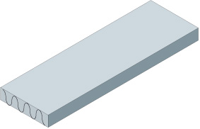
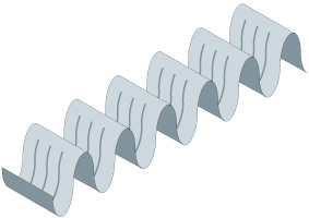
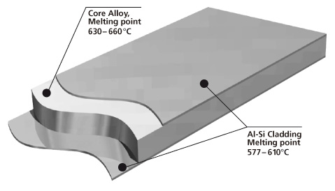
Brazing sheet comprises of a core alloy clad on 1 or 2 sides with a lower melting aluminum-silicon (Al-Si) alloy. This thin layer, usually makes up 5 % to 10 % of the total thickness of the brazing sheet.

It melts and flows during the brazing process, to provide upon cooling a metallic bond between the components. It is common that the braze clad alloy are from the AA 4xxx series or more particularly AA 4343 (Al-6.8~8.2 wt.% Si).

However, if larger fillets are desirable, or if in a situation where brazing is likely to occur at lower temperatures, AA‑4045 is the preferred choice.
Manufacturing

Cross-section morphology of a double-side clad tubestock.

Aluminium brazing sheet is manufactured by roll-bonding techniques to clad a core alloy ingot on one side or both sides with a low melting AlSi alloy. As an alternative, one side can be clad with a non-braze alloy, e.g. Zn-containing alloy.

Depending on the desired final properties, the core is either homogenized or not before the cladding operation.
The whole package is subjected to preheating, hot rolling and cold rolling down to the final thickness of the respective products. Depending on the requested final properties, the material is subjected to final annealing and / or intermediate annealing operation(s).

The core provides structural integrity. It is common to use a variety of aluminium alloys, examples being AA 3xxx (AlMn), more particularly AA 3003, AA 3005, AA 3105 and modified versions of AA 3003 or AA3005 (long life alloys).

Phase diagram
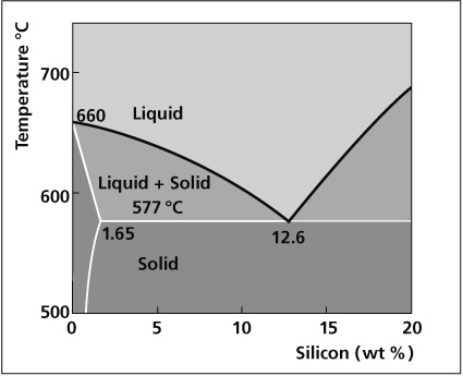
Aluminum End of Al-Si Phase Diagram

The melting characteristics of the cladding alloys are governed by the Al-Si phase diagram. The eutectic composition, i.e. the amount of Si required to produce the lowest melting point is 12.6%. The melting point at this composition is 577°C. At lower Si levels the solidus or the point at which melting begins is also 577°C. However, melting occurs in a range and the temperature above which the filler is completely molten is called the liquidus. In between the solidus and liquidus, the filler is partially molten, existing both as liquid and solid. The difference between the solidus and the liquidus forms the basis for various filler metal alloys.

The table below shows the solidus and liquidus of common brazing alloys.
[table id=2 /]

The higher Si alloys (e.g. AA4047) have higher fluidity and a narrower melting point range while the lower Si alloys have less fluidity with a wider, higher melting point range. Erosion of the base metal occurs when the braze alloy dissolves part of the core alloy. The extent of erosion is increased by:

  • Higher Si levels in the braze alloy
  • Longer braze cycles
  • Excessive peak brazing temperatures
  • Excessive thickness fo the braze metal layer
  • A design which allows pooling of the braze metal to occur

For added strength and machineability, certain alloys contain Mg. Most notably are the 6XXX series alloys (up to 1% Mg) that are used for fittings and machined components and the so-called long life brazing sheet alloys (up to 0.3% Mg in the core). There is a limit to the amount of Mg tolerated in NOCOLOK® Flux brazing. Up to 0.5% Mg can be tolerated in furnace brazing while around 1% Mg is tolerable for flame brazing.
When an Al alloy containing Mg is heated, the Mg diffuses to the surface and reacts with the surface oxide to form MgO and spinels of MgO:Al2O3. The diffusion is time-temperature dependent and is rapid above 425°C. These spinel oxides have reduced solubility in the molten flux. Furthermore, Mg and/or MgO can react with the flux forming compounds such as MgF2, KMgF3 and K2MgF4. All of these serve to poison the flux and significantly reduce its effectiveness.
In flame brazing, higher Mg concentrations can be tolerated since the faster heating rates do not allow the diffusing Mg enough time to appreciably decrease the beneficial effects of the flux. Flame brazing components containing > 1% Mg may be possible under some circumstances with increased flux loadings and very fast heating rates (<20 second braze cycle).
It should be noted that when one speaks of the brazing tolerance to Mg, it is the total sum of the Mg concentrations in both components:

[Mg] component 1 + [Mg] component 2 = [Mg] total

The figure below shows the effect of Mg on fillet size and geometry:

0.1% Mg

0.4% Mg

If the user is experiencing difficulties brazing and suspects elevated Mg levels as the cause, there are a couple of ways to be sure. First, check with the supplier of the alloys or perform a chemical composition analysis on the suspect alloys. This is the most certain way. Secondly, look for a golden hue on the brazed product. This is an indication that Mg alloys are being used and the color is a result of the increased oxide thickness. Furthermore, there may be a very light, almost fluffy residue on the brazed component that can literally be blown off by mouth. These visual indicators can most certainly be traced back to poor brazing results due to the presence of Mg.

Improving brazeability
There are a few ways in which the brazeability of Mg containing alloys can be improved:

  1. Increasing the flux loading. A substantial improvement is gained when increasing the flux loading up to 10 g/m2 or more in furnace brazing. In cases where there is just one component containing Mg such as in a fitting, extra flux can be brushed around the area of the joint.
  2. Increasing the heating rate. Slow heating rates allow more Mg to diffuse to the surface thereby hindering brazeability. For furnace brazing Mg containing alloys, the fastest possible heating rates achievable without sacrificing temperature uniformity will increase the tolerance to Mg.
  3. Combining increased flux loadings and faster heating rates.
  4. Maintaining proper gap tolerances and joint designs.
  5. Increasing the nitrogen flow rate to minimize furnace atmosphere contaminants that also compete to reduce brazeability.

Tip: NOCOLOK® Cs Flux

Better results are reported when using cesium containing fluxes for aluminum alloys containing Mg up to 0.6 – 0.8% Mg. Fewer leaks are observed when compared with standard flux and less porosity is noted in the joint areas. Furthermore, standard flux loads and braze cycles can be used with Cs containing fluxes.

NOCOLOK® Cs Flux is a flux of the general formula KxCsyAlFz where Cs is chemically bound. It has a melting range of 558°C – 566°C. The maximum Cs content is limited to 2% to keep the cost of the flux down. Increasing the Cs content does not increase brazeability as shown below:

Cesium reacts as a chemical buffer for Mg by forming CsMgF3 and/or Cs4Mg3F10. The flux inhibiting factors of Mg are therefore reduced.

Aluminum alloys are classified according to their alloying elements. The Aluminum Association designations are listed in the table below:

Designation System for wrought aluminum alloys
Alloys series   Description or major alloying element
1xxx                  99.00% minimum Aluminum
2xxx                 Copper
3xxx                 Manganese
4xxx                 Silicon
5xxx                 Magnesium
6xxx                 Magnesium and Silicon
7xxx                 Zinc
8xxx                 Other Element
9xxx                 Unused Series

The chemical composition of each AA alloy is registered by the Aluminum Association and a few examples are listed:

Example of aluminum alloy composition limits in weight percent*

[table id=1 /]

*Maximum, unless shown as a range

How to measure?

In the case of heat exchangers, the surface area being fluxed must first be determined. For ease of calculation, the louvers on the fin can be ignored. The radius on the fin can also be ignored.

Imagine then the fin pulled out of the heat exchanger and straightened out to form one long strip. Similarly, the surface area of the slots in the header can also be ignored.

Remember that in calculating the surface area of the heat exchanger, there are 2 sides to every tube, 2 sides to every fin and 2 sides to the headers. The total surface area is then expressed in m2: All dimensions are in meters (m) to yield a surface area in square meters.

Header


Assuming it is a cylindrical (condenser) header:

SA (m2) = (2 x 3.14 x radius of header(m)) x length of header (m) x 2 headers

Assuming it is a radiator header:

SA (m2) = length of header (m) x width of header (m) x 2 (sides/header) x 2 (headers)

Tubes

SA(m2) = width of tube(m) x length of tube (m) x 2 (sides/tube) x total number of tubes

Fins

Ignore the louvers in the fins

SA (m2) = width of fin (m) x (fin height (m) x number of fin legs/tube) x 2 ( sides/fin) x total number of fins

Total Surface area in m2 = SA headers + SA tubes + SA fins

To determine the flux loading, a degreased and thoroughly dry heat exchanger is weighed. The heat exchanger is then run through the fluxer, blow-off and dry-off section of the furnace. The heat exchanger is removed just prior to entering the brazing furnace and weighed again.

The flux coating weight is then determined using the following formula:

Weight of unit fluxed and dried (g) – weight of unit un-fluxed (g) x Surface area (m2)

To make sure that the flux loading was determined on a completely dry unit, run it through the dry-off section a second time and re-weigh.

See also: Flux loading

Brazing aluminium to copper is common in the refrigeration industry where copper tubes are brazed to aluminium roll-bond panels or tubes. To join aluminium and copper using brazing technology and standard NOCOLOK® Flux, flame brazing would be applicable (as well as using a low-melting flux with a low-melting filler metal). It is very similar to brazing aluminium to aluminium, but some precautions are necessary.

However, when copper is brazed to aluminium and the heating process takes too long, the copper will diffuse into the aluminium at the joints. A low melting Al-Cu alloy (Al-Cu33 eutectic temperature 548°C) is thus formatted, and this could lead to erosion by perforation.

Therefore, during the brazing process, the flame should never be directly applied to the joint, because the heat should be transferred by conduction through the parts to be brazed. As soon as the filler metal begins to melt, the flame must be quickly removed.

A second issue with brazing copper to aluminium is that the aluminium has a much lower melting point than copper (Al: app. 650°C; and Cu: above 1000°C). Therefore, the flame is usually directed on the copper. Nevertheless, once the heat transferred from the copper to the aluminium reaches the melting range of aluminium, it will start to burn down very fast, while the copper is still taking the heat. The formation of the above mentioned low melting Al-Cu alloy accelerates the destruction of the aluminium components.

Consequently, flame Brazing of aluminium to copper is a delicate process and requires some experience. But it is used by many companies for large scale production. But it is next to impossible in furnace brazing. There are no conventional furnace designs which will cool quickly enough to halt the continual formation of the aluminium-copper eutectic. For this reason, brazing copper to aluminium in a furnace is not practiced.

There are three different ways to provide (or generate) filler metal in flame brazing of aluminium to copper.

  • Use of Al-Si filler alloy (Al-Si 12 – AA4047). Standard procedure like in flame brazing of aluminium to aluminium – just a little bit faster to avoid burn-through.
  • Rely on the formation of Al-Cu alloy during the brazing cycle. If this method is used, a support provided by a thin Stainless Steel tube along the interior joint area can provide additional structural integrity.
  • A pre-heated copper tube is inserted very fast into an aluminium tube. The mechanical energy released will generate additional heat. Abrasion of surface oxide by the inserted tube promotes the formation of Al-Cu filler alloy. This process works with and without flux (however, results are better with flux).

1. Have a clean surface

2. Heat the joint evenly to brazing Temperature

3. Choose the right brazing alloy for the job

4. Select the appropriate means of removing the oxide skin from the faying surfaces of the joint

5. Use a capillary gap of the appropriate size

6. Apply the brazing alloy to the last part of the joint to reach brazing temperature.