As manufactured, a non-corrosvie K-Al-F-type flux typically is a mixture of potassium tetra-fluoroaluminate (KAlF4), and also contains potassium penta-fluoroaluminate (K2AlF5). K2AlF5 exists in different modifications: potassium penta-fluoroaluminate hydrate (K2AlF5 · H2O), and hydrate-free (K2AlF5).
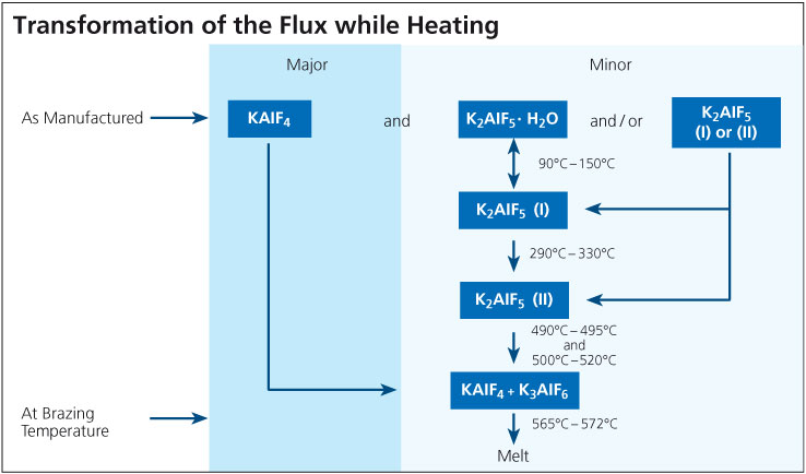
During the brazing process, the material undergoes essential physico-chemical alterations. While the chief component, KAlF4, is simply heated up, the compound K2AlF5 · H2O begins to lose its crystal water from 90°C (195°F) on. When the temperature is further increased within the ranges of 90° – 150°C (195°F – 302°F), and 290°C – 330°C (554°F – 626°F), two different crystallographic (structural) modifications of K2AlF5 are formatted.

When the furnace temperature is raised above 490°C (914°F), K2AlF5 begins to react chemically. According to the equation:

2 K2AlF5 → KAlF4 + K3AlF6 (Equation 1)

the exact amount of potassium hexa-fluoroaluminate (K3AlF6) necessary for a eutectic flux composition (i.e. mixture of two or more substances which has the lowest melting point; see phase diagram) is obtained from the original K2AlF5 content. At brazing temperature, the resulting flux composition has a clearly defined melting range of 565°C to 572°C (1049°F – 1062°F). The flux melts to a colorless liquid.
Due to a vapor pressure of 0.06 mbar at 600°C, some of the KAlF4 evaporates during the brazing cycle, particularly once melting temperature is reached. The total content of KAlF4 contained in the exhaust is depending on time and temperature. Based on results from TGA analysis (with a heating rate of 20°C/min), the quantity of volatile compounds in Flux between 250°C and 550°C (482°F and 1022°F) is approximately 0.2 to 0.5%. These flux fumes contain fluorides and have the potential to react with the furnace atmosphere, especially moisture, to form hydrogen fluoride according to the equation:

3 KAlF4 + 3 H2O → K3AlF6 + Al2O3 + 6 HF (Equation 2)

This is one of the reasons, why the brazing process should take place in a controlled atmosphere (nitrogen) with low dew point and low oxygen level (another reason is to minimize re-oxidization effects on the aluminum surfaces).

Directly after brazing has been completed, flux residues consist mainly of KAlF4 and K3AlF6. In the presence of moisture from the surrounding atmosphere, the K3AlF6 is converted back to K2AlF5 · H2O over time (several days) in a reaction reverse to the one described in equation 1 followed by a re-hydration step.

The schematic below illustrates the transformations that occur as the flux is heated to brazing temperature. Note that these phases are unstable outside the furnace atmosphere.
Process related causes

The service life of a heat exchanger may be shortened due to corrosion caused by process related events. Some examples are listed below:

Excessively high brazing temperature or too long time at temperature will lead to excessive Si diffusion in the core. Si diffuses along grain boundaries and this can increase the susceptibility to intergranular corrosion. By maintaining proper time-temperature cycles and thereby minimizing Si diffusion, intergranular attack can also be minimized.

Copper in contact with aluminum will cause a corrosion related failure very quickly. Copper is noble (cathodic) to aluminum and when these two metals are in contact in the presence of an electrolyte, the aluminum will be consumed rapidly. This may occur in a heat exchanger manufacturing facility where both Al and Cu heat exchangers are produced and there is cross-contamination of process routes. It only takes one small Cu chip to land on the surface of Al during some part of the manufacturing process to cause a short-term failure in the Al heat exchanger. If both Al and Cu heat exchangers are to manufactured under the same roof, it is recommended (and practiced) to physically separate the two production routes with a wall and take extensive steps to avoid cross-contamination.

Carbonaceous residues can be generated on the heat exchanger surfaces during the heat cycle from residual lubricants, excessive use of surfactants, binders in flux or braze pastes etc. Carbon plays very much the same role as Cu in that it is noble to Al. In a corrosive environment, carbon residues act as a cathode and Al as an anode, leading to the galvanic corrosion of Al. The best preventative measure is to ensure that the heat exchangers are thoroughly and properly cleaned and degreased prior to brazing. This includes monitoring the flux slurry bath for any signs of organic contamination (for instance oil slicks).

Coatings

Painting a heat exchanger offers some level of corrosion protection, but is primarily used for cosmetic purposes. Painting will enhance corrosion protection if it covers the entire heat exchanger uniformly and is free from defects. In fact, paint defects or stone chips will accelerate corrosion locally. Many Al producers believe it is better to leave the heat exchanger unpainted to prolong its service life.

Conversion coatings such as chromate or phosphate conversion coatings work differently than painted surfaces. Conversion coatings enhance the natural oxide film on Al, essentially making it thicker and more resistant to hydrolysis. These types of coatings are most often used with automotive evaporators.

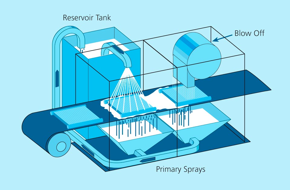
In its simplest form, a slurry is held in a reservoir tank and continuously agitated to prevent settling. The slurry is pumped, usually with air-diaphragm pumps to the flux slurry cabinet where the heat exchangers moving on a conveyor are sprayed with the slurry. After spraying, the excess flux slurry is blown off in a separate chamber with high volume air. The over spray and blown off slurry is recycled back to the reservoir tanks, again using air-diaphragm pumps.

Depending on the sophistication desired, a second flux spray chamber may be installed after the first chamber to deliver a higher concentration slurry to problem areas such as tube to header joints in condensers and radiators. This second spray chamber would have a separate flux delivery system and a separate reservoir tank to contain the higher concentration flux slurry.

The components of the flux delivery system including reservoir and agitators should all be constructed of stainless steel or chemically resistant plastics (nozzles for instance). There should be no mild steel or copper containing components – includes brass or bronze – in contact with the flux slurry. The schematic below shows the components of a generic fluxing station:

Wet Fluxing

Note that splashing will occur inside the fluxing cabinet and cause an accumulation of dried flux on the walls. Therefore the cabinet is washed with water periodically to remove this accumulated flux. The frequency of this maintenance operation is up to the manufacturer, but could be anywhere from once per shift to once per month.

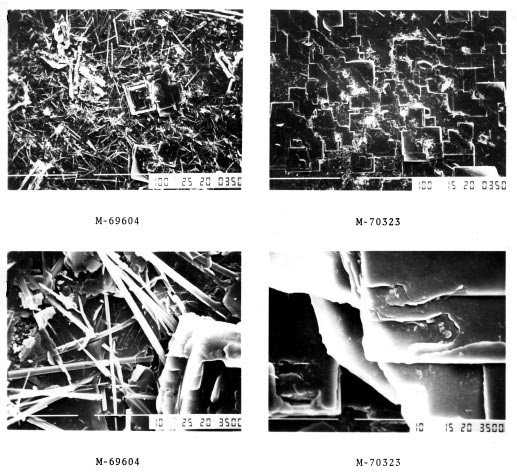
The general appearance of NOCOLOK® brazed parts can range from relatively bright to light grey depending on the flux loading and furnace dew-point. When either is increased excessively over recommended levels, the appearance moves towards the grey colour. The flux residue usually can not be seen by the naked eye, however, it is visible under a microscope at 50x magnification. Higher magnification SEM views of the flux residue are shown in the pictures below.

SEM photomicrographs of NOCOLOK flux residue

SEM photomicrographs of NOCOLOK flux residue

The pictures on the left are typical of a tunnel furnace brazed surface, needle-like in structure possibly including the odd flat platelet. The pictures identified M-70323 are typical of a furnace atmosphere containing higher than recommended levels of O2 specifically during the cooling cycle in a batch furnace. The morphology is almost 100% flat platelets. This surface has been reported to have better corrosion resistance in service.

Other flux residue properties are as follows:

a) Residue Thickness

Typically 1–2 microns. This can vary depending on flux coating weight prior to brazing.

b) Hardness

The residue hardness is about 4 on the Mohs scale.

c) Adhesion

No measurable loss has been found in circulation tests with freon or glycol type coolants using recommended flux loading. However there are reports that some detachment may occur where higher than recommended flux loading is used, particularly where molten flux pooled in downside areas.

d) Wettability

The post-braze flux residue has a hydrophilic (wetting) surface, however that wettability decreases with time.

e) Corrosion Resistance

The presence of flux residue on the part surface mildly increases corrosion resistance under normal conditions.

f) Solubility

Solubility of flux residue is influenced by the method of measurement. A typical value are between 1.2 and 3.0 g/l with Al, F and K ion concentrations approaching the stoichiometry of the compound KAlF4 .

g) Post-Braze Odour

There is a slight odour from minute amounts of H2S immediately after brazing. It disappears within a short time. If objectionable, the odour may be eliminated by rinsing the part with water.

h) Post-Treatment

The flux residue provides a good base for coatings. However, thicker residues resulting from higher than recommended flux loading can result in the poor or non-adhesion of wet or dry powder paint coatings.

NOCOLOK® Flux residue is not easily removed from the surface of brazed parts. Mechanical abrasion, such as wire brushing or grit blasting, can be used to clean off heavier flux residues from „robust“ joints. No practical chemical cleaning solution has been found. Boric acid and nitric acid solutions at higher temperature will partually remove the residues, however the times required (~ 1 hour) and the dangerous fuming with nitric acid preclude their use. Basically, the best procedure is to flux the product properly so that there is no visible after-braze residues and therefore no flux removal required.

Very often, heat exchanger manufacturers increase the flux loading on components to be brazed to compensate for furnace atmosphere or other process related deficiencies. The flux is an excellent “band-aid” and can be used as such, but only while the true problems are located and rectified. Long term use of higher than recommended flux loads can lead to other problems.

Over fluxing causes more KAlF4 evaporation and condensation. This will load up the dry scrubber more quickly. White powder will accumulate more quickly on the curtains at the exit end of the furnace. If this is noticed, there is a very good chance that the dry scrubber is loading up more quickly.

There will be a more rapid build-up of the flux inside the furnace. This is a common issue with over fluxing whereby flux builds up on the muffle floor at the entrance to the cooling zone where it will solidify. This flux build up has been known to deflect the mesh belt.

There is more rapid build up of the flux on the fixtures which can significantly reduce maintenance intervals.

Over-fluxing can lead to visible flux residue on the brazed heat exchanger which may increase the incidence of flux residue fall-off. Excess flux residue dulls the appearance of a brazed heat exchanger and can also accumulate in the gasket areas causing problems with seals. Too much flux residue will also inhibit surface treatments such as painting or conversion treatments.

The theoretical amount of flux required to dissolve a 100 Å oxide film is about 0.02 g/m2
(1 Å = 10-10 m = 0,1 nm). For a 400 Å film, still only 0.08 g/m2 flux is required. These do not take into account losses to moisture, oxygen or poisoning of the flux by Mg alloy additions.

In practice however, the recommended loading for fluxing is 5 g/m2, uniformly distributed on all active brazing surfaces. This is more than 250 times the theoretical amount required for oxide dissolution. To visualize what 5 g/m2 flux loading might look like, think of a very dusty car. As the heat exchange manufacturer gains experience with his products, he may find that a little more is required for consistent brazing or that he can get away with a little less flux.

Too little flux will result in poor filler metal flow, poor joint formation, higher reject rates, and inconsistent brazing. In other words, the process becomes very sensitive.

Too much flux will not affect the brazing results. However there will be pooling of flux which can drip on the muffle floor, the surface of the brazed product will be gray and there will be visible signs of flux residue. Furthermore, flux will accumulate on fixtures more rapidly which then requires more frequent maintenance. More importantly yet, using too much flux will increase the process costs.

In some cases, heat exchanger manufacturers use higher than recommended flux loadings to mask furnace atmosphere deficiencies. This should be viewed as a short-term solution and the furnace problems should be addressed.

See also: How to evaluate flux load?

Based on currently available information, there is no simple cleaning method for flux residues by washing or dissolving – i.e. there is no suitable solvent or chemical solution – without attacking (corroding) the substrate material as well.

Mechanical Cleaning
Usually, removal of flux residue can only be done by mechanical means. From solid surfaces and from robust joints, as well as from Stainless Steel fixtures, the flux residues can be mechanically removed by sand or grit blasting. Wire brushing is a second alternative for flux residue removal. We recommend using Stainless Steel wire brushes for cleaning. Rotating SS-wire brushed are suitable too – provided the surface areas are accessible. Brushes made from copper and brass should only be used when the cleaned surfaces are not exposed to any subsequent welding or brazing cycle any more, because copper traces from the brush (even dust particles) in contact with aluminum can cause severe erosion problems.

Chemical Cleaning

Flux residue has a slightly higher solubility in strong alkalis and some acids. But in many cases the base materials (aluminum or Stainless Steel) will be attacked (corroded) by these chemicals too.

A solution of hot boric acid (10 to 15%, 75 – 80°C) can be used to remove some of the flux residue from brazed assemblies. Aluminum dissolution by boric acid is relatively moderate. The immersion time necessary to remove the bulk of residues varies from 10 to 30 minutes. But even then the flux residue removal will not be 100% successful.

Handling (preparation and usage) and discharging (waste disposal) of such chemical solutions can be problematic and expensive – due to their corrosive properties and the subsequently necessary waste water treatment. Considerations for health, safety and environment must be in accordance with the Safety Data Sheets.

Ultrasonic cleaning

Ultrasonic treatment may be effective in removing flux residues, provided that the parts to be cleaned fit into the ultra sonic dipping bath. A detergent (cleaning agent) can be added to the solution to improve the cleaning activity. The use of Antarox BL 225 for ultrasonic cleaning treatment is probably feasible. However, when there are any other additional chemicals mixed with the Antarox-containing cleaning solution (particularly when adding acids or alkalis) their compatibility with Antarox must be verified.

There are commercial solutions available for ultrasonic cleaning of Stainless Steel. More information on this subject is available from suppliers for industrial cleaning chemicals.

Summary

Flux residue from NOCOLOK Flux can only be removed by mechanical means, i.e. using wire brushes or grit/ sand blasting. This is a very difficult and laborious procedure – and a very dirty one (dust formation!). Local exhaust and ventilation is needed in the work area where the parts are cleaned. There is no suitable solvent to take off the flux residue without corroding the base materials.

Dust and dirt, condensates, lubricants and oils must be thoroughly removed. If the metal work pieces are poorly prepared, the flux will not spread evenly and the flow of filler alloy will be haphazard: it will either not spread properly or will discolour. The consequence would be an incomplete joint.

The first step is therefore: always clean the components of all oil and grease. The surfaces can be cleaned using either chemical, water-based or thermal cleaning techniques and substances.

Aqueous Cleaning

Aqueous or water based cleaning is a quite efficient and robust process, but still generates some waste water.

Aqueous cleaning starts off with a concentrated metal cleaning agent, which is subsequently diluted with water to 1% to 5% (v/v). The composition of a supplier’s cleaning solution is proprietary, but usually contains a mixture of surfactants, detergents and active ingredients such as sodium carbonate that serves to elevate the pH. Once diluted, the cleaning solution will typically have an elevated pH in the range of pH 9 to 12. There are acid based solutions, but appear to be less common.

The best water-based cleaners contain water, tensides, cleaning agent and active ingredients such as carbonates.

The cleaning solution works best at higher temperatures and is usually recommended to operate at 50°C to 80°C. Cleaning action is quicker at higher solution temperatures.

Thermal Degreasing

Thermal degreasing works by elevating the temperature of the work piece so that lubricants present on the surfaces will be evaporated. This procedure only works with special types of lubricants known as evaporative or vanishing oils. Vanishing oils are light duty lubricants used mostly for the fabrication of heat exchanger fins, although they are now finding uses in the stamping and forming of other heat exchanger components. Lubricants not designed for thermal degreasing must not be used. These could leave behind thermal decomposition products and carbonaceous residues which at higher level prevent brazing and have the potential to degrade product appearance and accelerate corrosion.

When brazing aluminum to stainless steel using:
a) NOCOLOK® Flux and Al-Si filler alloys are suitable
or
b) alternatively CsAlF-Complex flux (melting range between 420 and 480°C) and Zn-Al filler alloys.

Regarding a): Brazing of aluminum to stainless steel works both with NOCOLOK® Flux + Al-Si filler alloy and with NOCOLOK® Sil Flux. After the flux melts and the oxides are removed, there is a reaction between Al and Fe, forming a thin intermetallic layer of FeAl3. This layer forms the metallurgical bond between the Fe and Al components. FeAl3 is very brittle and thus the thickness of this layer should be minimized, otherwise the joint can easily fracture.

From a metallurgraphic point of view, there is a multi-layer system (microscopic structures). First, there is the stainless steel, then the layer of FeAl3, then the Al/Si filler metal, and finally the aluminum base material. The thickness of the brittle FeAl3 layer is a function of brazing time and temperature; – consequently the need for a short brazing cycle with fast heat-up and very short holding time at maximum temperature. Too high brazing temperatures must be strictly avoided. Only with a short brazing cycle, successful joining of aluminum to steel is possible.

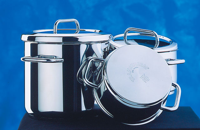
Joining of Al to steel using NOCOLOK® Flux is done on large scale commercially for the production of pots and pans (stainless steel pots with aluminum ‚compensation base plates‘) – mostly in induction brazing. It is also used for the production of heating elements (steel heating plates with aluminum base plates and tubes for the electrical heating wires). Another application for aluminum to steel joining is brazing of large aluminum-plated steel tubes – up to 11 meters long – with aluminum fins for power plant cooling modules.

In the manufacturing of pots and pans where there is a large surface area between the Al base plate and the pot, a mixture of filler metal powder and flux is often used. This circumvents the use of filler metal shim stock which is said to be costly and difficult to implement. In Al tube to steel or stainless steel tube joining, conventional flame brazing techniques can be used. Filler metal wire, either pre-placed or fed into the joint must be used. In the production of power plant cooling modules (with aluminum-plated steel tubes), the filler alloy is provided by clad fin material.

The following article provides some answers on general questions regarding the use of NOCOLOK Sil Flux for manufacturing pots and pans.

What is the NOCOLOK Sil Flux quantity (per m²) required for sandwich brazing or pressure cookers (stainless steel to aluminium)?
The recommended load for NOCOLOK Sil Flux is approximately 15 to 25 g/m². Brazing aluminium to stainless steel requires rapid processing, i.e. very fast heating ramp and short time at brazing temperature. Usually, this can only be accomplished with induction brazing.

When brazing aluminium to stainless steel using NOCOLOK Sil Flux, the Sil Flux first forms the filler metal from the aluminium component. The filler metal then reacts with the stainless steel to form a thin layer of FeAl3.

From a metallurgraphic point of view, there is a multi-layer system (microscopic structures). First, there is the stainless steel, then the layer of FeAl3, then the Al/Si filler metal, and finally the aluminium substrate. The FeAl3 layer is very brittle, and so it is important that this layer is kept as thin as possible. The thickness of this layer is a function of time and temperature,- consequently the need for a short brazing cycle.

Brazing of Stainless Steel with Aluminium

To prepare a NOCOLOK Sil Flux slurry or paste: What is the exact mixing ratio (flux to solvent) required?
The mixing ratio for NOCOLOK Sil Flux slurries or pasts depends on the application method on site. In some cases, the main focus is a specific viscosity for an automated fluxing system. In other cases, only small flux quantities are prepared for immediate consumption.

NOCOLOK Sil Flux can be prepared with alcohol (ethanol or isopropyl alcohol) or alcohol/ water mixtures (70% alcohol content) in any ratio from 20 to 60 wt% (solids). As mentioned earlier, the actual slurry concentration will depend on the application procedure. The objective is to achieve 15 to 25 g/m² surface area.

If the NOCOLOK Sil Flux slurry is not completely consumed within one or two days, we recommend using pure alcohol as carrier to avoid any chemical reaction between the solvent and the metal powder (silicon). Due to hydrolysis of the silicon powder, water should not be used to prepare NOCOLOK Sil Flux paste.

Brushing, dipping or spraying can be utilised to apply the flux. Uniformity of the applied flux coating is very important.

How fast after applying NOCOLOK Sil Flux, the components should be processed for best results?
Before the part is heated up, the NOCOLOK Sil Flux slurry or past coating on the component surfaces should be thoroughly dried or allowed to evaporate. If alcohol is used as a carrier, the evaporation will only take a few seconds (with 15 to 25 g/m² flux load). NOCOLOK Sil Flux is non hygroscopic (i.e. the flux does not attract and absorb moisture) and non-corrosive (i.e. there is no reaction between the flux and the metal surfaces at room temperature). If a water mixture is used as the flux carrier, the components must be dried after flux application to avoid water-based corrosion effects.

What is the grain/ particle size distribution of the silicon metal powder in NOCOLOK Sil Flux?

The silicon particles in NOCOLOK Sil Flux show a particle size distribution curve with most of the grains within a range of 10 to 45μm. The Solvay specification for NOCOLOK Sil Flux (fine grade) – which is used for brazing pots and pans – is as follows:
< 5μm: < 25%
10 to 20μm: 50%
> 35μm: < 10%
> 74μm: not detectable (by laser particle size analysis)

What are the key points regarding product fit-up for good joint formation in NOCOLOK Sil Flux technology?

During the brazing process it is important that the components to be joined are in intermediate contact with each other. There must be firm pressure applied on all the surfaces of the plates throughout the brazing cycle to avoid large voids and gaps. Filler metal can only fill gaps up to a certain width (i.e. approximately 0.10 to 0.15 mm).