1. Preparation and Application

This article provides information about the application of binder systems for NOCOLOK Flux.

Solvay offers three concepts for flux binder application:

  • NOCOLOK Binder (water-soluble) / NOCOLOK Thickener (water-soluble)
  • NOCOLOK System Binder (water-based)
  • NOCOLOK Flux plus Binder Mixture (water-based)

These products can be used in water-based NOCOLOK Flux slurries to improve flux particle adhesion. This is of particular interest for fluxing of pre-formed components prior to assembly in order to reduce flux fall-off and dust formation. Binders are also helpful to pre-coat certain areas with specific flux loads. All binder mixtures can be applied on external and internal surfaces.

During the brazing cycle, these binders will completely evaporate (mostly between 350 and 400°C). When used as described below, there will neither be detrimental interactions between the binder and the flux, nor between the binder and the aluminum surfaces. Trials have shown that even at four-times the standard flux load with a binder mixture there was still no surface discoloration after brazing.

2. General Comments

The surface areas to be coated with binder mixtures must be free of lubricants, oils, dirt, and dust. Means of application include spraying, dipping, and brushing.

All NOCOLOK Flux binder mixtures can be applied by spraying with a suitable spray gun (1.4 mm – 1.6 mm) at approximately 3 – 5 bar pressure.

The surface temperature should be at least 10°C.

When binders are used for flux application, the recommended flux load for good brazing results is the same as it is for the standard process (i.e. between 3 – 5 g/m2). The thickness of the binder coating is usually between 10 – 30 μm.

Drying can be done in air – requiring approximately 15 – 20 minutes at room temperature for the coating surface – and 50 – 60 minutes before the parts can be handled. Oven and forced convection drying is feasible too: at 50 – 80 °C, parts will dry within 5 – 20 minutes.

Please refer to the MSDS for detailed information regarding the safe handling of the product.

3. Preparation of Binder Mixtures

For all binder concepts and preparations, the mixtures should be prepared or opened immediately before consumption.

To prepare a mixture free of agglomerates and to achieve best coating results, the following procedures must be observed for either binder concepts:

  • NOCOLOK Binder / NOCOLOK Thickener
    • 45 parts (wt%) de-ionized water (as used for preparing standard flux slurries) is mixed thoroughly with
    • 15 parts (wt%) NOCOLOK Binder (water-soluble) and
    • 5 parts (wt%) NOCOLOK Thickener (water-soluble).
    • Once the first three components are completely homogenized,
    • 35 parts (wt%) NOCOLOK Flux powder are added successively under continuous agitation.
  • NOCOLOK System Binder
    • NOCOLOK System Binder (water-based) already contains the binder and thickener component as well as water. Consequently, only NOCOLOK Flux powder must be added.
    • 65 parts (wt%) NOCOLOK System Binder (water-based) plus
    • 35 parts (wt%) NOCOLOK Flux.
  • NOCOLOK Flux plus Binder Mixture
    • NOCOLOK Flux plus Binder Mixture (water-based) is a ready-for-use preparation containing NOCOLOK Binder, NOCOLOK Thickener and NOCOLOK Flux powder.

If necessary, the mixtures can be passed through a sieve prior to use. This will remove any potential agglomerates.

Prior to use the flux powder in the mixture must be suspended. The thickener will prevent the flux powder from settling too fast, however, when stored for some time or diluted, the mixture must be well shaken before spraying.

The binder component is activated by oxygen from air. Once sprayed and dried, the product cannot be recycled or reused.

Any remaining flux / binder mixture should be stored in an airtight and sealed container. We recommend consuming the mixtures within one week after mixing.

4. Additional Information:

  • NOCOLOK Binder, -Thickener, and –System Binder are compatible for standard NOCOLOK Flux, -LM Flux, -Cs Flux, and -Sil Flux. They are not suitable for NOCOLOK CB Flux and -Zn Flux due to chemical reactions between these fluxes and the ingredients.
  • The formulations (mixing ratios) provided in Solvay’s technical information sheets and brochures are intended as general recommendations – They provide the best basis for automated spray application and have been tested with good brazing results.
  • The recipes can be adjusted to specific application needs by changing the mixing ratios within certain ranges.
  • A well balanced ratio of binder and thickener to flux in the mixtures is important for good brazing performance:
  • Higher binder ratios result in a harder coating layer and stronger flux adhesion. But they require more care for the binder removal step.
  • Very high binder and/ or thickener ratios increase the organic content in the mixture – which may result in carbon residues (discoloration) after brazing.
  • It is possible to reduce and/ or to increase the water content of the mixtures – resulting in higher respectively lower viscosity.
  • Water dilution will cause less wetting action and reduced adhesion.
  • A surfactant (wetting agent) is part of the binder formulation – providing uniform coating, and – compensating (to some extent) for surfaces not cleaned prior to application.
  • Thickener is used for adjusting the viscosity and to keep the flux powder longer in suspension – This provides better performance in spray application. Nevertheless, formulations can be prepared and used without the addition of thickener.
  • Cleaning before binder-based flux application is recommended – but not mandatory.
  • A clean surface can be coated more easily and the flux adhesion will be better.
  • Residual oils and lubricants are reducing binder activity and require higher flux load.
  • Higher surfactant levels can compensate for some contamination – but result in more foaming.

5. Binder Flux Mixing Ratios

  • The standard composition is 35% NOCOLOK Flux, 15% NOCOLOK Binder, 5% NOCOLOK Thickener and 45% water. If a product with lower flux ratio is wanted (i.e., with only 10% flux), the composition must be modified. Right now, we are proposing 10% flux, 8% binder, 2% thickener and 80% water. There is only limited experience with this composition, and we are a little concerned. The reasons for our concerns are as follows:
    • With 35% flux, the ratio of flux to binder/ thickener on the surface of the headers is sufficient to combat the effects of the high organic content. Also, 15% binder has reasonable adhesion characteristics.
    • At 10% flux, the ratio of flux to binder/ thickener must be modified; otherwise there may not be sufficient flux to combat the high organic content. This is why we propose to reduce the binder and thickener to 8% and 2%, respectively. In other words, too much binder/ thickener and not enough flux may lead to black deposits on the headers after brazing and/ or difficulties in brazing.

6. Warehousing Considerations and Shelf Life

  • Under standard storage conditions, the shelf life is up to 12 months and probably longer. Standard storage conditions means that the product was stored at less than 30°C, as suggested in the MSDS.
  • The binder product can be stored at a temperature higher than 30°C, but the shelf life will shorten due to premature aging. Therefore, we recommend that the binder products be consumed within six months, if the storage temperature is a constant 40°C. This is not based on experimental data, but on general knowledge of water based polymer systems and adhesives. Any product stored at a temperature higher than 40°C should be consumed more quickly.
  • Under no circumstances should the binder products, in their original packaging, be exposed to a temperature of 60°C or above. We suspect that polymerization will occur, agglomerates will form and the performance will drop.

7. Thermo-Gravimetric Analysis (TGA) for Binder Flux

Please refer to the flyer “NOCOLOK Flux Application with Binders”.

8. Recommendations for Reducing Costs

  • Is not possible to only mix the binder, thickener and flux and just add the water on site. Without the water, the flux/ thickener/ binder mixture forms a rubbery-like substance that is very difficult to work with.
  • The least expensive option is to purchase the binder and thickener separately and do mixing of all ingredients on site. The most convenient option is to have a ready-mix, ready-to-use product supplied.
  • Please see above for additional recommendations for mixing.

Summary

The article was written on the basis of frequently asked questions from companies which either wanted to start a new all-aluminium brazing production of heat exchangers or wanted to convert from copper and aluminium mechanical assembly design to all-aluminium brazed parts. The questions were grouped into three main categories: Equipment (emphasis on assembling process), Process (emphasis on different fluxes and fluxing methods) and Corrosion.

Specific production challenges are also presented, which are important not only to newcomers of all-aluminium brazed heat exchangers, but to established companies as well. These include typical brazing problems such as managing leaks and the basics of brazing copper to aluminium. These topics are discussed by their relevance to the brazing parameters and their role in successful brazing.

Content:

  1. Introduction (in this issue)
  2. Equipment (in this issue)
  3. Brazing process (in August issue)
  4. Brazing copper to aluminium (in September issue)
  5. Corrosion resistance (in September issue)
  6. Summary (in September issue)

1. Introduction

Brazing Furnace

Increasing environmental concern has identified the air conditioning and refrigeration industry as one of the contributors to the greenhouse effect and ozone depletion.

Accordingly to [1] 15% of all electricity consumption in the developed world is used by the air conditioning and refrigerator industry. Increasing the efficiency of these heat transfer systems has the positive impact of decreasing electricity consumption and therefore the overall emission of CO2. The advantages of all aluminium brazed condensers in an air conditioning system are well described in [2]. For example one such case study [3] allowed for saving about 2700 USD during 6 months. The above advantages are currently well recognized by both the air conditioning manufacturers and their end users. It is our observation that the majority of the companies in the HVAC industry which have started or are about to start production of aluminium brazed heat exchangers have only limited experience with aluminium brazing; therefore providing them with maximum possible technical assistance from the supplier side is of high importance.

This article was written on the basis of our contacts with such companies having an aim to offer some assistance to all newcomers and companies facing some troubles with their new type of production.

2. Equipment

In most cases, the first question from a company that wants to start a new aluminium brazing activity is: “What kind of furnace should I buy?”

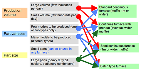
It is a complex issue which mainly depends on size of the products, its diversity and overall planned production volume. The general principles for the choice of the brazing furnace are shown in Fig. 1. It should be pointed out that the furnace manufacturers will make a brazing furnace customized to particular requirements of a given client.

Fig. 1: Basic principles for brazing furnace choice

Fig. 1: Basic principles for brazing furnace choice

Assembling units

In many cases the companies which are starting production of all aluminium brazed heat exchangers have been producing copper brazed heat exchangers. Therefore the natural question is: ”Can I use the same equipment which is used for copper units?”

The straight forward answer is: No! Aluminium requires high precision for assembling (recommended gap size is 0.1 to 0.15mm), which is hardly ever achieved for brazing copper parts. Also one should remember that any copper contamination on aluminium can cause catastrophic brazing failures (holes).

The process of component assembly can be done on a simple manual stacker or on machines with varying degrees of automation through to fully automated units. The level of automation should be mainly determined by the planned production volume, but also other factors such as local labour costs should also be considered.

Basic requirements for a manual assembling unit:

  1. Cores must be assembled on a perfectly flat heavy steel plate
  2. After laying out the tubes and fins, the tubes must be pushed precisely into position determined by the slots in the headers.
  3. To secure the above requirement:
    1. movement of the pusher must be allowed only in one direction (no side or up movement),
    2. travel distance must be accurately controlled – e.g. by mechanical block on the pusher,
    3. it is useful to have a special distances between tubes to secure the right spacing for each header slot,
    4. the vertical alignment of the tubes must be secured either by steel plate or by hammering the tubes with a special pad.
  4. Threading the headers on the tubes should be done in one single action which does not allow for any side or vertical deflection of the headers.
  5. After threading the headers the fixtures should be assembled and the tube pusher released.

The process of the part assembly is invariably connected with fixtures; these are the steel elements which hold the parts together during brazing and then removed after brazing. The most frequently asked question is: ”What should be the design of the brazing frames/fixtures?”

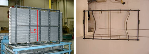
Basically there are rigid and elastic designs which allow for some expansion when the core is heated. For larger cores elastic design is preferred. This type of fixture is reusable, also known as a permanent fixture and can go through the brazing cycle several hundred times. Apart from that we could use single usage fixtures, known as disposable fixtures and these include steel wire and steel bands. The multi-use fixtures must be made of stainless steel and in most cases the single use fixtures are usually made of ordinary low carbon steel.

Fig. 2: Example of rigid and elastic fixtures

Fig. 2: Example of rigid and elastic fixtures

When designing the length of the fixture (distance marked in red as Ls in fig. 2, one must remember thatthere is a difference in thermal expansion coefficient between aluminium and steel. To compensate for this, the following assumption is made: The length of the steel fixture at brazing temperature must be equal to the nominal width of the aluminium exchanger at brazing temperature. On this basis, an equation can be used describing the linear change of dimensions with temperature.

Ls(1 + αstΔt) = Lo(1 + αalΔt)

Where:
Ls – length of steel fixture,
αst – thermal expansion coefficient for the fixture material,
αal – thermal expansion coefficient for aluminium,
Δt – Increase of the part temperature during brazing,
Lo – Nominal width of the part.

As an example, for a part having width of 900 mm and nominal tube spacing of 8 mm, solving this equation and taking into account the fact that after assembly there must be some pressure exerted by the fixture on the part, the length of the fixture should be 907.5 mm and the fin height 8.08 mm. The longer steel fixture is compensated by the increased fin height. It also means that after assembly the part will have a slightly barrel-like shape (bowed out at the sides).

The question: ”What final checks are required for brazed parts?”is also connected to equipment purchases. All brazed parts must be checked for leak tightness. The most simple method is the so called “under water test”. In this case the part is pressurized with air and lowered into a water bath to look for bubbles. However some end users require more accurate and reliable methods. In the automotive industry it is common to check condensers for leaks with high pressure and extremely sensitive helium leak detection devices.

Each product should be accepted by the end user. In every case the scope of acceptance tests should be agreed to between the manufacturer and the end users. Typical tests include burst pressure, thermal cycling and of course standard ones for heat transfer efficiency and pressure drop. As a general rule it can be said that all aluminium parts should meet all the requirements applied to copper/brass parts.


References:

1. Hans W. Swidersky, “Brazed Aluminium Heat Ex-changers for the Refrigeration and Air Conditioning Industry”, APT Aluminium News, 1-2009

2. Bjørn Vestergaard, “Brazed Aluminium Heat Ex-changers – Ask for the inexpensive features”, Seminar “Aluminium Process-Technology for HVACR Industry” Vienna, March 21st-23rd, 2007

3. Case Study – Harris County Sheriff’s Building, “Carrier Turn to the Experts” 2006 Carrier Corporation 05/06 04-811-10206

Will be continued…

The NOCOLOK dictionary was the reference book for the brazing of aluminium at its release over a decade ago. Now it has been completely revised and published under the name NOCOLOK Encyclopedia, with many additional chapters including a chapter on special fluxes. Within the new, fresh and tidier design lies concentrated knowledge for technicians and users in the aluminium industry. Many illustrations help make complex processes more understandable.

The PDF file is fully linked and keywords are quickly found using the built-in Acrobat Reader search function. The encyclopedia is free of charge and available for download.

NOCOLOK-Encyclopedia-Cover

In a flux delivery system, the distances that the flux slurry has to travel is often very short and there is no time for the flux slurry to settle out in the lines or header pipe of the nozzle array. However, if the flux slurry must be conveyed over long distances, to the waste water treatment site at the other end of the plant for instance, then great care must be taken to prevent the lines, drains, pipes and troughs from becoming clogged with settled out flux. The flux slurry is a suspension and unless continuously agitated, the flux will eventually settle out.

If the flux slurry must be conveyed over long distances, it is perhaps better to separate the flux and water with some sort of filter arrangement in the neighborhood of the fluxing station. The solids can be collected near the fluxing station and the particulate free wastewater can then be easily transported.

A second option is to transport the used flux slurries batch-wise (in drums) to the treatment facility or where ever desired. This eliminates all concerns about flux settling out in troughs or other parts of the plumbing system.

In recent years, the topic of what to do with wastewater from fluxing operations has gained a lot of attention in light of heightened environmental awareness and compliance. Years ago, wastewater from cleaning slurry booths, waste flux slurries etc. were simply diluted and dumped down the drain. Some manufacturers are still following this practice, but it is become less and less common. Today, the heat exchanger manufacturers are faced with what to do with wastewater more and more.

Some manufacturers collect the waste slurries and effluent from cleaning out the fluxing stations and allow the flux to settle out. The water phase is then decanted and collected until a sufficient volume is collected. At that point, a waste disposal company is called in to collect and treat the contaminated water. This is an expensive, but in many cases a necessary option. If the collected water is relatively clean and not contaminated with oil, it may be reused to top up flux slurries. The only problem here is that one must be certain that there are no other contaminants in the wastewater other than flux ions. If there are other contaminants (and there almost certainly will be), tests should be performed to ensure that these will not in any way interfere with the brazing process.

Solvay Fluor also developed a continuous process to reuse and recycle wastewater in a fluxing operation. It is based on the principles described above, only in a continuous fashion:
Lauzon, D.C., Swidersky, H.W., “Methods for Eliminating Wastewater from Flux Slurries in Non-Corrosive Flux Brazing”, VTMS 2001-01-1764, pp 649-654, 2001.

Selective Pre-Fluxing with Adhesives – Fashion or Progress

Summary

Over the last 15 years, selective prefluxing – also called paint fluxing or binderbased fluxing – has evolved as an alternative method for applying flux powder in the aluminium brazing industry. There are many activities to define process parameters of fluxing with adhesives.

The first part of this paper outlines key features of prefluxing. The methodology for measurements of physical characteristics of binders and paint flux mixtures are described. General rules for behaviour of flux paints in brazing process are discussed together with some examples of flux paint features.

In the second part a case study is shown to illustrate common challenges when brazing with flux paint. The third and last part of this paper provides a cost comparison as guidance for choosing the right fluxing method for two different cases, one being extremely negative and the second as a positive case.

4. Flux Paint Risk Point

The fundamental condition for successful brazing is having a substrate surface which is well wetted by a molten filler alloy. Any binder as an organic compound contains carbon. This carbon must be removed before brazing, otherwise it will form a very thin deposit on the substrate surface preventing wetting by the molten filler alloy2. When the flux paint is deposited on open surface areas, like for example on the radiator headers, there is no issue to remove the binder by evaporation at higher temperature. However, when the flux paint is applied in enclosed spaces, like for example on inner surfaces of condenser manifolds, the removal of binder becomes challenging. Proper de-bindering conditions must allow the binder fumes to escape completely. Residual binder – like any other trace organic – carbonizes during the brazing cycle – causing surface discoloration and potentially poor brazing.

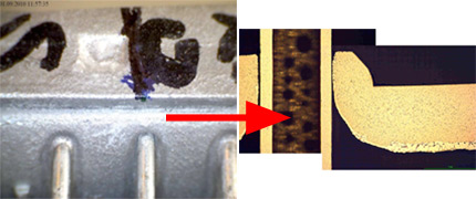
Fig. 5 shows a leak in the tube apex. The condenser manifold was made of two halves: cover and header. Only the cover part was prefluxed by immersion. Composition of the flux paint: flux ~ 30%; carrier (acetone) ~ 62%; binder (polymethyl methacrylate) ~ 12%.

Fig. 5: Leak in tube to manifold joint in condenser with manifold half flux painted by immersion.

The gap size between the tube and manifold is in the range of 40µm, which is well within the maximum recommended tolerance.

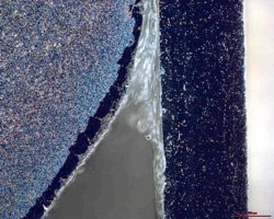
Fig. 6: Dark field image of the non brazed tube to manifold joint.

Dark field image of the non brazed joint showed that the gap is filled with transparent substance. Investigation by Scanning Electron Microscope revealed that the joint was completely filled with post braze flux residue.

Fig. 7: Mapping of potassium in the non brazed area of the joint.

The tube surface presented in Fig. 7 shows very uneven flux distribution. There are areas completely free of potassium (flux) and areas covered with a layer of flux. This would indicate that the tube surface was not completely wetted by flux upon application. Such “poisoning” of the surface can appear when it is contaminated with carbon. Though the overall level of carbon (as examined be SEM) is low, its distribution is uniform. The carbon most likely originated from binder traces. It seems that during debindering treatment the carbon got embedded into the aluminium oxide layer. Such a modified aluminium oxide layer is more difficult for the flux to remove.

5. Example of cost comparison calculation

The major reason behind the decision to introduce flux painting technology should be reduced overall cost of the manufacturing process. These should include:

  • Media
  • Maintenance
  • Environment (cost of waste utilization)
  • Raw material and consumables
  • Labor
  • Investment cost (depreciation)

In the following section we will present two examples of such calculations. It must be pointed out that the quoted numbers, though not far away from the values one can see in an aluminum brazing factory, may always differ from case to case. Thus the presented calculations should be considered only as a tool in which individual data needs to be fed, not as an indication which fluxing method is better.

Case A: Condensers

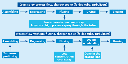
In the modified condenser production, the tube to fin joints are realized by tube precoating with NOCOLOK Si Flux3 – while the manifolds are prefluxed with a water based flux paint. This concept allows for complete elimination of the fluxer and the thermal degreaser from the brazing line. The dryer then acts as preheat and oven, where partial debindering takes place.

Fig. 8: Standard and modified process flow for condenser production.

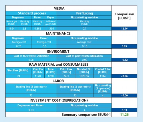
Table 3 shows assumed input values like for example cost of electricity and the difference between the cost of standard process and modified one in the above listed categories. The whole calculation is done in an excel table where one can play with different input data which shows how sensitive the overall cost is to a change in a given parameter. In this case analyses showed that the most sensitive factor is the cost of the Sil Flux precoated tubes. Change of price in tube material by 10% can entirely reverse the final result.

Table 3: Example calculation for standard and modified condenser manufacturing. Production level 200 pcs/hour.

Case B: Charger Coolers

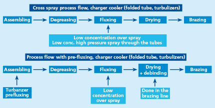
Charge Air Coolers have one characteristic feature. Inside the tubes there are turbulators to make the flow of the hot compressed air more turbulent to increase the transfer of heat from the air to the tube walls. A condition to secure sufficient tube resistance to the inner pressure is to have all turbulators uniformly brazed to the inner tube surface. This requires fluxing of the tube’s internal surface. The most robust method is fluxing by immersion. This however produces higher post brazed flux residue levels and it is usually a bottle neck in the continuous production flow.

The other method is to apply a high pressure spray of flux slurry across the tubes. When combined with cross blow of high pressure air it secures proper inner fluxing even up to 900mm long tubes. This method does not slow down the production flow in a continuous line. For comparison the latter cross spray fluxing method is compared with prefluxing of turbulators. It should be remembered that wet fluxing is applied on tube to fin joints in both cases.

Fig. 9: Standard and modified process flow for charger coolers production.


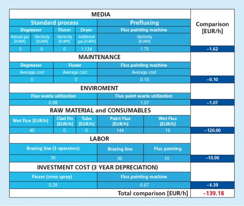
Table 4: Example calculation for standard and modified charge air cooler manufacturing. Production level 200 pcs/hour.

In this example there is no major change in the brazing line and as a matter of fact an additional entirely separate operation is added. This situation is somewhat improved when the flux painting process of the turbulators is incorporated into the tube making unit; however it eliminates only the negative effect of additional labor. The major cost is connected with consumption of flux paint. On average the cost of flux paint is about 20% higher than the cost of flux. Assuming liquid flux paint consumption of 4 grams per one turbulator and 50 grams of flux powder used on one charge air cooler fluxed by cross spray we will end up with such high difference in cost. In spite of this fact there are production lines which use the flux painting applied on turbulators.

6. Summary and conclusions

During recent years, the concept of prefluxing with binder flux/ paint flux has become quite popular as a method for fluxing. However when taking a decision about choosing this technology, the following aspects should be considered:

  • What level of adhesion is required?
  • Are we going to deal with binder removal from enclosed spaces?
  • Is the binder vapor going to affect my equipment?

and the most important one:

  • will there be real cost benefits?

In the case of cost calculations for NOCOLOK Sil Flux coated extruded condenser tubes the major factor influencing the overall cost is the cost of the coated tubes. Though the presented calculation is only an example and can slightly vary from case to case, it is the authors‘ opinion that in certain cases the introduction of this technology can be justified by cost savings. In the case of flux painted turbulators for charge air coolers, the major factor influencing the overall calculation is the cost of flux paint. It seems that such process is not always justified from the cost point of view.

7. References / Literature

1 Swidersky, H. W., Aluminum Brazing with Non-Corrosive Fluxes – State of the Art and Trends in NOCOLOK Flux Technology, Tagungsband, Hochtemperaturlöten und Diffusionschweißen, DVS-Berichte Bd. 212, Düsseldorf: DVS-Verlag, pp. 164-169, 2001

2 Hawksworth, D. K., A Study of Organic Residues on the Surface of Vacuum Brazing Sheet, 2nd International Congress Aluminium Brazing, Düsseldorf 2002, conference proceedings

3 NOCOLOK Sil Flux: fine grade and extra fine grade

Dumping
With continuous use, a flux slurry will eventually become contaminated. So far, there is no data that correlates the level of accumulated contaminants with poor brazing. Therefore, it is better to be on the safe side rather than wait till the number of rejects rise due to a contaminated or dirty slurry. It is therefore recommended that a slurry should be dumped when there is visual evidence of contamination. If there is an oil slick floating on top of the slurry in the reservoir or when it is discolored, the slurry should be dumped and replaced with fresh slurry. Alternatively, to avoid misjudging the quality of slurry visually, the slurry could be dumped at regular intervals, especially if the manufacturer knows that the cleanliness of the heat exchangers entering the fluxing booth is not ideal. Experience will dictate how often the slurry should be dumped.

Note however that some heat exchanger manufacturers almost never dump their flux slurries or if they do it might be only once per year. This is only the case when the heat exchangers are very well degreased prior to entering the fluxing booth and efforts are made to avoid undue contamination of the slurry. Simply keeping the cover closed on the slurry tank reservoir will keep out airborne contaminants and lengthen the slurry life.

What to do with the used flux slurry is treated covered under wastewater.

Flux Recovery – Recycle and reuse?
Around the flux slurry preparation station or around the perimeter of the fluxing booth, there will inevitably be some flux on the floor. The inclination is to sweep up this flux and throw it into the flux slurry reservoir or back into the flux drum. This action should be avoided at all costs. Any flux that falls on the floor should be disposed of promptly. The reason is that there are too many contaminants in a manufacturing environment that can affect brazing or cause other damage. Cigarette butts, paper clips, dust, dirt, oil, paper and so on can all have very damaging effects to the flux delivery system and on the brazed products. If the flux is on the floor, dispose of it and do not reuse it.

Spilled Flux

Flux powder on the plant floor should be collected by vacuum cleaners equipped with high efficiency particulate air (HEPA) filters, dedicated central vacuum systems or a wet vacuum system. Avoid sweeping and the use of compressed air. Small wet spills may be mopped up. To remove large spills the floor should be hosed down with water. Waste and contaminated water must be disposed of in accordance with local regulations.

De-ionized (DI) or reverse osmosis (RO) water is recommended to make up the flux slurries. This is to avoid long-term accumulation of mineral deposits in the flux delivery system that can cause blockage of nozzles and/or inadvertently drop on the heat exchanger. Furthermore, local plant or city water may contain ppm levels of contaminants such as chloride and copper that are detrimental with respect to corrosion performance. Other contaminants may also be present which can affect brazing. Furthermore, to avoid any seasonal variations in water quality, to avoid variations in water quality between manufacturing locations and so on, it is highly recommended that DI or RO water is used to make us flux slurries.

Water analysis recommended

In general, it is difficult to comment on potential effects of trace impurities in the flux slurry water without knowing more details about the character of the contamination. There may be only very little influence on the brazing results even with 1,000 μScm-1 conductivity. However, it is necessary to perform a chemical analysis of the water for further evaluation in each case.

The use of de-ionized water has always been recommended to prevent scale build up in the flux delivery system. Reverse osmosis (RO) water is also used successfully. There are no recommendations on conductivity or maximum hardness values (except those related to the calcium levels as listed below). The only reference Solvay Fluor can provide is the conductivity of the de-ionized water used at our Technical Services and Analytical Department in Hanover, which is below 0.2 μScm-1.

As far as we know, no scientific study was yet conducted to determine water quality requirements for aluminum brazing. In collaboration with Alcan, Solvay Fluor has established guidelines for maximum impurity limits for water quality based on contamination which might interfere with brazing or cause discoloration of the brazed parts:

[table id=3 /]

For Chloride a maximum of 0.02% is specified (corrosion problems). Based on experiences at some customer locations with post braze odor in the past, Sulfates should be below 0.02%. Phosphates can cause problems with post braze odor too, due to the potential formation of PH3. Silicates are known to interfere with flux activity. Borates and Silicates can cause black spots on post braze flux residue.

Residual hydrocarbons on all aluminum surfaces should be limited to the lowest level possible, due to the potential formation of carbonaceous residue and the long term corrosion problems caused by this residue. The same applies to all other carbon containing trace impurities in the system.

Most of the above information refers to flux and flux slurry contamination. However, it also relates to other additives and chemicals in the process, particularly when those additives cannot be,- or are not-, removed from the fluxed component prior to reaching brazing temperature.

Selective Pre-Fluxing with Adhesives – Fashion or Progress

Summary

Over the last 15 years, selective pre-fluxing – also called paint fluxing or binder-based fluxing – has evolved as an alternative method for applying flux powder in aluminium brazing industry. There are many activities to define process parameters of fluxing with adhesives.

The first part of this paper outlines key features of pre-fluxing. The methodology for measurements of physical characteristics of binders and paint flux mixtures are described. General rules for behaviour of flux paints in brazing process are discussed together with some examples of flux paint features.

In the second part a case study is shown to illustrate common challenges when brazing with flux paint. The last part of this paper provides a cost comparison as guidance for choosing the right fluxing method for two different cases, one being extremely negative and the second as a positive case.

3. Overview of Binders

Group Adhesion providing components Co-solvents / dispersion agents (examples only) Carriers / solvents
1 Polyurethane (aqueous polyurethane dispersion) N-Methyl-2-pyrrolidon water
2 Water-based acrylic 3-Methoxy-3-methyl-1-butanol water
3 Solvent-based acrylic 1-Methoxy-2-propyl acetate and others Preferably non-explosive and non-flammable organic solvents (e.g. esters of dicarboxylic acids)

Table 1: Main groups of flux binders / flux paints.

One of the most important characteristic of a binder is the kinetics of binder removal. This property is measured by a method called Differential Thermal Analysis [DTA]. The specimen (binder or flux paint) is placed in a small crucible and heated with a preset rate. The device measures the change of weight of the specimen and heat emitted or absorbed by the sample. The test can be done in air or at a chosen gas atmosphere.

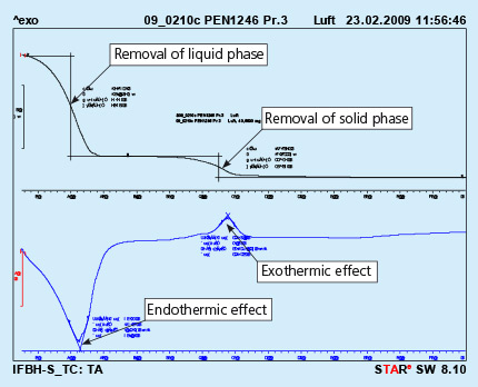
An example of the curves obtained in such device is shown in Fig. 1

Fig. 1: DTA curves obtained from solid flux paint sample. Test performed in air. 

The upper curve represents lost of weight upon heating, and the lower curve represents thermal effects appearing in the heated sample. The endothermic effect is associated with evaporation of the sample and the exothermic effect is usually connected with burning of the sample.

It should be observed that the above curves represent a sample of liquid flux paint. The removal of the the liquid phase (carrier evaporation) takes place during curing of the painted part. This process is always done before putting the parts into the brazing line. For flux paints made with water as a carrier it is simple evaporation.

Removal of the solid phase (cured binder) takes place at much higher temperature then evaporation of the carrier. It usually happens in the brazing line – in the dryer and partially in the brazer. Kinetics of the solid phase removal is shown in Fig. 2. In this case the analyzed sample is prepared by painting a metal surface, curing the paint and careful scratching off the solid paint, which is then analyzed in DTA device.

Fig. 2: DTA curves obtained from liquid flux paint sample. Test performed in air. 

As can be seen the end of the binder removal is in the temperature range of 450oC. The above presented curves show the removal of binder at a constant heating rate of the sample (in this case 10oC/min). In the brazing line the prefluxed parts firstly go through a dryer where the temperature for dry parts is usually in between 200oC to 250oC. The parts for a continuous brazing line usually stay in the dryer no longer than 10 minutes.

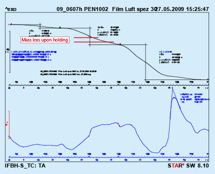
To simulate this condition, a dry flux paint sample was analyzed by DTA with a hold for 10 minutes at 300oC. As can be seen from Fig. 3, holding at constant temperature for a prolonged time does not lead to full removal of the binder. In the given case only about 36% of the binder was removed.

 Fig. 3: DTA curves with holding time 10min. at 300oC Test performed in air.

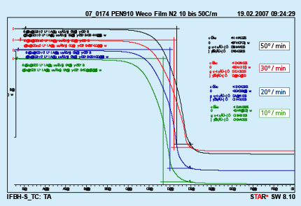
Different furnace design and different size of the brazed parts are responsible for different heating kinetics in the brazing lines. An influence of different heating rates on kinetics of binder removal is shown in Fig. 4.

Fig. 4: DTA curves with different heating rates Test performed in nitrogen. 

The curves presented in Fig. 4 were obtained from analyzing a polyurethane binder heated in nitrogen atmosphere. It can be seen that only the middle temperature is moved to higher values with increased heating rate. The beginning and end of the debinding process do not depend on the heating rate.

Several examples of debinding temperatures for different type of binders are presented in table 2.

Binder Type Tested in Air Tested in Nitrogen
Middle temp. [°C] End Temp. [°C] Weight loss [%] Middle temp. [°C] End Temp. [°C] Weight loss [%]
Polyurethane Binder A 355 530 99.7 370 460 99.6
Polyurethane Binder B 360 550 98.5 370 460 97.5
Acrylic Binder C (water soluble) 317, 382 450 87.2 220, 387 430 85.2
Acrylic Binder D (high adhesion) 267 420 Not measured* 385 Not measured* 27.5
Acrylic resin Binder E 275 400 86.9** 370 450 89.3**
* DTA performed only on ready mixtures
**Lower values due to some flux residue (sample obtained from ready mixture)

Table 2: Examples of debinding temperatures for different types of binders.

Will be continued soon.

Preparation

In the simplest operation, the lid is removed and flux is manually scooped out of the drum (with a  large plastic scoop) and added to the flux slurry reservoir tank. The flux should always be added to water and never scooped into an empty tank. Aerosolization should be controlled by a local exhaust ventilation system (LEV). The operator will likely need to wear a dust respirator and PVC gloves, goggles and an adequate protective coverall.

For large volumes of flux slurry preparation, it is also common to dump the entire drum contents into the reservoir with a forklift truck. Again, care should be taken to avoid dusting and aerosolization.

All slurries must be agitated to hold the flux particulate in suspension. Allowing the flux particles to settle out in the mixing tanks or containers will result in inconsistent flux loadings. During a shutdown period (maintenance, holidays etc.), the agitators may be turned off. Upon start up, it must be ensured that all settled flux is brought back into suspension prior to starting the fluxing operation. Ideally, the flux slurry should be slowly agitated during shutdown for ease of start-up.

Agitation

Since the flux is insoluble in water and the goal is to keep the flux in suspension, the natural tendency is to use high agitation speeds which creates high shear forces. The high shear forces will break up particles of flux and over time (even a few hours), shift the particle size distribution to smaller particles, even to the sub-micron range. These very small particles tend to be „sticky“ and when collected in one place, will acquire a gel like appearance. Furthermore, once the flux has acquired this sticky property, it is very difficult to bring this flux back in suspension after a shut-down period.

These effects may be seen even if the speed of the agitator has not changed, but the slurry consumption has decreased (e.g. one less work shift per day). In other words, the same flux is being agitated for a longer time than before and therefore may be shifting to a smaller particle size as a result of the increased residence time in the tote.

The key to agitation for flux slurries is low speed – low shear agitation to just keep the flux in suspension. Faster is definitely not better when it comes to keeping the flux slurry suspended.

Flux which has acquired a gel like consistency caused by high shear stresses may lead to strainer clogging. Even if the individual particles are small enough to pass through the mesh, once one particle sticks to the screen, others will stick to it and eventually accumulate to such an extent as to clog the strainer. Gelled flux is very difficult to bring back into suspension because it does not break up easily – the flux sticks to itself. This gelled flux will clog a small mesh size strainer in no time at all. The stickiness of sub-micron particle size flux has been associated with many blockages and is often seen to clog nozzles.

Large agglomerates are most often formed by the flaking off of flux that has dried on the walls of the spray cabinet or other nearby structures such as exhaust hoods. The best practice to avoid the formation of these agglomerates is to have a regular clean-out procedure. When this practice is not carried out, flux solids will settle out within individual droplets and form clumps or agglomerates. These agglomerates can be very hard and are also often associated with blockages.