Approach to non-corrosive fluxes for further reduced residue solubility and improved magnesium tolerance
Technical Information by Ulrich Seseke-Koyro, Hans-Walter Swidersky, Leszek Orman, Andreas Becker, Alfred Ottmann
We split the article in four parts:

  1. Abstract and Basic Experimental Laboratory Procedures
  2. Reduced Flux Residue Solubility
  3. Improved Magnesium Tolerance
  4. Summary and Outlook

Improved Magnesium tolerance

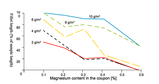
Mg additions to Al alloys contribute to higher strength properties. The ongoing trend in saving weight by down-gauging of Al sheet thickness requires sufficient mechanical stability. One option for the production of higher strength Al alloys is to increase the Mg content.

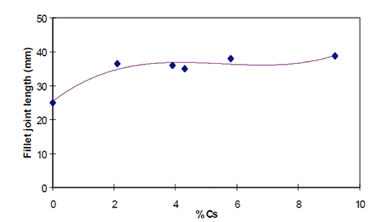
A disadvantage of Mg is the interaction with potas-sium fluoroamuminate fluxes during brazing, which results in poor joint formation [3] [4]. This effect, known as “flux poisoning”, is caused by the formation of high melting compounds. The addition of caesium and other metals to the flux helps to compensate to a certain degree the poisoning [6].

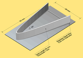
For the first set of laboratory brazing experiments we chose commercially available AMAG 6951 brazing sheet (0.68% Mg, 4343 clad) and clad-less AMAG angle material (0.68% Mg) to investigate the brazing performance and joint formation. In this situation the metal-to-metal interface adds up to 1.36% Mg (2 x 0.68%) in total.

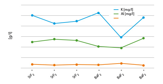
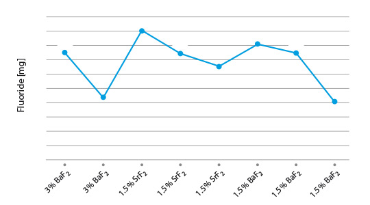
Table 1 shows a list of representative flux combina-tions with NOCOLOK® types, KAlF4, Li3AlF6. CsAlF4, and AEFs.

We repeated all brazing tests with each sample three times.

Flux Type Load Fillet visual validation Comment
NOCOLOK® Cs Flux 10 g/m2 100% very small joint inconsistent seam
MD001212 LiCs24 10 g/m2 100% small joint weak seam
MD001223 LiCs43 10 g/m2 86% small joint inconsistent seam
AB039215 KAlF4/BaF2 10 g/m2 52% small joint inconsistent seam
NOCOLOK® Cs Flux 15 g/m2 100% weak seam
MD001212 LiCs24 15 g/m2 100% thicker than with NOC Cs Flux
MD001223 LiCs43 15 g/m2 100% thicker than with NOC Cs Flux
AB039215 KAlF4/BaF2 15 g/m2 98% weak seam slighly better than NOC Cs Flux

Table 1: Brazing trials: AMAG clad – AMAG clad-free angle different flux blends based on KAlF4 plus BaF2/Li3AlF6/CsAlF4

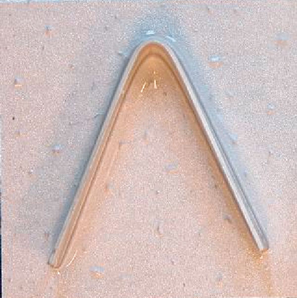
The angles from most of the AMAG specimens could be removed after brazing by pulling. Only a broken inner and outer fractured seam line was left – as can be seen below in picture 1 a.
flux_residus_part3_1
flux_residus_part3_2
flux_residus_part3_3

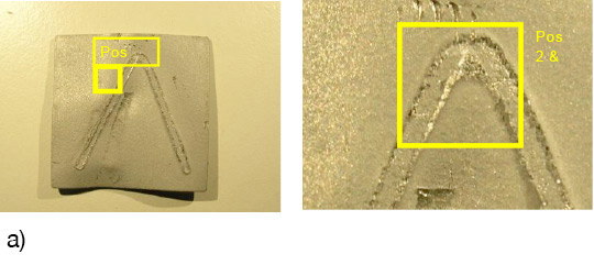
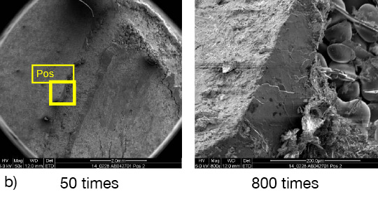
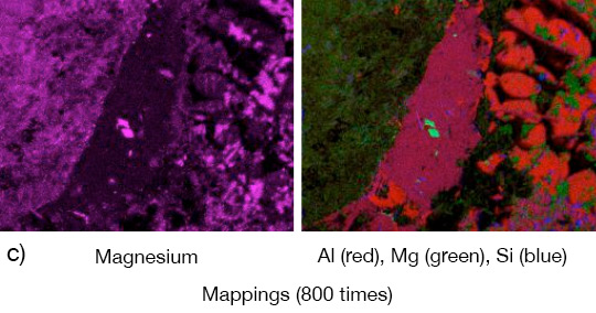
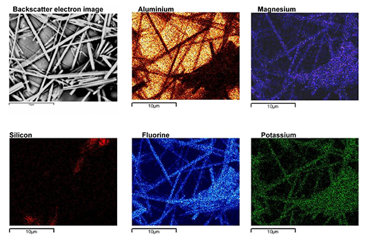
Picture 1: a) Photos, b) and c) SEM/EDX of NOCOLK® Cs Flux brazed sample (load 15 g/m²) Coupon 0.68% Mg, angle 0.68% Mg – angle removed by pulling

From the SEM analysis it is evident that a proper met-allurgical joint between base and angle has not been formed.

flux_residus_part3_4
flux_residus_part3_5

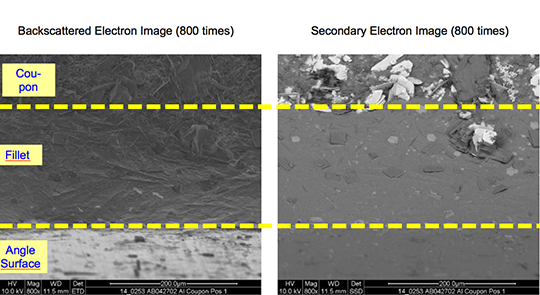
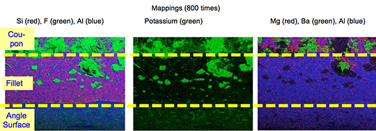
Picture 2: SEM/EDX analysis of aluminium ‘angle on coupon‘ brazed with KAlF4/BaF2 blend

There is flux residue present in the pulled apart fillet. This indicates that the liquid filler alloy was not capa-ble of pushing out completely the flux of the joint and it could be an explanation for the weakness of the fillet.

However, in case of the blend MD001212 LiCs24 with load 15g/m2 the joint structure is thorough as can be seen in picture 3 a).

flux_residus_part3_6

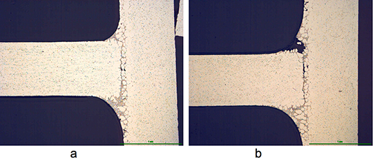
Picture 3: Microstructures of the brazed joints
a) Flux MD001212, load 15g/m2
b) Flux MD001223, load 15g/m2

It is worth mentioning when connecting blocks are brazed to condenser manifolds often a high load of manually applied flux is used in order to overcome the high Mg content in the block material. For such a case using the mixture MD001212 would allow for having quite high Mg content in the block material, which can be required by the designers of condens-ers.

The total concentration of 1.36% Mg (joint interface) is probably too high, because for most brazing applica-tions, a flux load of 15g/m2 is impractical. Thus, we decided to reduce the level of Mg in our samples to half – i.e. to 0.68% – by switching to an AA1050 (Al 99.5%) angle. We also reduced the flux load to a more process-typical level of 5g/m². The results are listed in table 2:

Flux Type Load Fillet visual validation Comment
MD001212 LiCs24 5 g/m2 100% good seam
NOCOLOK® Cs 5 g/m2 87% small joint

Table 2: Brazing tests AMAG coupon (0.68% Mg)/Al99.5 angle

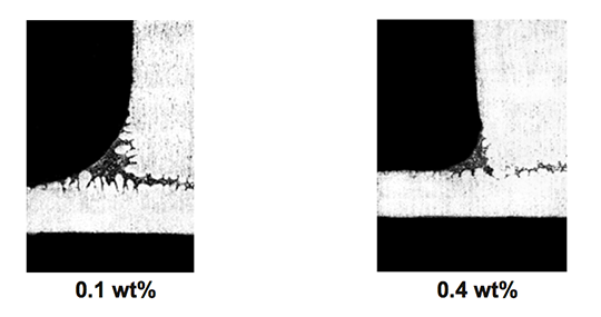
The structure of the joint cross section below (picture 4) obtained with flux MD001212 LiCs24 shows good quality.

flux_residus_part3_7

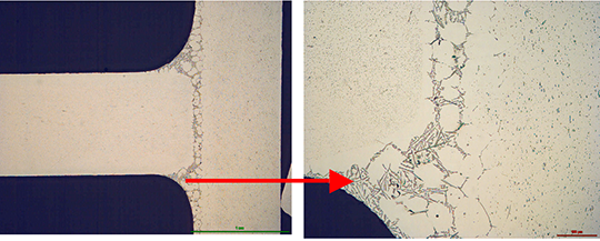
Picture 4:Joint cross sections of alloys containing 0.68% Mg brazed with MD001212 LiCs24, load 5g/m2

To be continued…


  1. P Garcia et al, Solubility Characteristics of Potassium Fluoroaluminate Flux and Residues, 2nd Int. Alum. Congress HVAC&R, Dusseldorf (2011)
  2. P Garcia et al., Solubility and Hydrolysis of Fluoroaluminates in Post-Braze Flux Residue, 13th AFC Holcroft Invitational Aluminum Brazing Seminar, Novi (2008)
  3. J Garcia et al, Brazeability of Aluminium Alloys Containing Magnesium by CAB Process Using Cs Flux, VTMS5, 2001-01-1763 (2001)
  4. H Johannson et al, Controlled Atmosphere Brazing of Heat Treatable Alloys With Cesium Flux, VTMS6 C599/03/2003 (2003)
  5. Handbook of Chemistry and Physics; Ref. BaSO4: 0.0025 g/l
  6. U Seseke, Structure and Effect – Mechanism of Flux Containing Cesium, 2nd Int. Alum. Brazing Con., Düsseldorf (2002)

Approach to non-corrosive fluxes for further reduced residue solubility and improved magnesium tolerance
Technical Information by Ulrich Seseke-Koyro, Hans-Walter Swidersky, Leszek Orman, Andreas Becker, Alfred Ottmann
We split the article in four parts:

  1. Abstract and Basic Experimental Laboratory Procedures
  2. Reduced Flux Residue Solubility
  3. Improved Magnesium Tolerance
  4. Summary and Outlook

Reduced Flux Residue Solubility

The water solubility of standard NOCOLOK® Flux is 4.5 g/l, whereas for post-braze flux residue (pbr) it is 2.7 g/l. Post-braze residue of NOCOLOK® Li Flux shows a solubility of 2.2 g/l [1].

In the periodic table of chemical elements the group I fluorides have a reasonable low solubility (LiF: 2.7g/l [20°C]), but their Al-F-complexes much lower (Li3AlF6: 1.1g/l , K2LiAlF6: 0.3g/l with about 183 mg F-/l, K3AlF6: 2g/l), the group II fluorides (Alkaline Earth Fluorides “AEF”) show very low solubility (MgF2: 0.13g/l, CaF2: 0.016g/l, SrF2: 0.12g/l [25°C], BaF2: 0.12g/l [25°C]) [5]. Based on the facts of the dissolution behaviour of NOCOLOK® Li and the much lower solubility of the AEFs, we started investigating combinations of potas-sium fluoroaluminate fluxes with selected AEFs to combine the brazing characteristics of NOCOLOK® type flux with the very low solubility of AEF.

NOCOLOK® Flux consists of potassium fluoroalumi-nates with a specific ratio of KAlF4 and K2AlF5. Each of these compounds has different solubility. The combination of the (pure) compounds with different AEFs was of our main interest. We melted and pulverized the flux blends, dissolved them in a defined amount of DI-water and analyzed for K, Al and F.

The data achieved form these experiments is illus-trated in figure 1:

Flux-Residue-dia-1

Fig. 1: Solubility of flux blends – melted and pulverized
(lines are used to illustrate differences of the blends)

Considering minor statistical variations, the results look quite reasonable, with the blend of NOCOLOK® Li/BaF2 showing the lowest K value. This observation can be explained by the low solubility of NOCOLOK® Li Flux. Of more relevance is the actual post-braze solubility (flux residue) on brazed Al surfaces. Interactions of base material and molten filler metal may have a more complex chemical impact on the solubility behaviour

The results from coupon brazing under laboratory conditions and the solubility of the flux residue can be seen in figure 2.

Flux-Residue-dia-2

Fig. 2: Post-braze fluoride solubility of selected flux/ AEF combinations on Al coupons
(lines are used to illustrate differences of the blends)

Among the combination of NOCOLOK® type fluxes with diverse AEF additions, KAlF4/BaF2 shows the lowest residue F– solubility, i.e. 4mg/l. All our laboratory brazing tests with the samples showed the same good results like with standard NOCOLOK® Flux.

Corrosion comparison tests will be subject for future investigations.

To be continued…


  1. P Garcia et al, Solubility Characteristics of Potassium Fluoroaluminate Flux and Residues, 2nd Int. Alum. Congress HVAC&R, Dusseldorf (2011)
  2. P Garcia et al., Solubility and Hydrolysis of Fluoroaluminates in Post-Braze Flux Residue, 13th AFC Holcroft Invitational Aluminum Brazing Seminar, Novi (2008)
  3. J Garcia et al, Brazeability of Aluminium Alloys Containing Magnesium by CAB Process Using Cs Flux, VTMS5, 2001-01-1763 (2001)
  4. H Johannson et al, Controlled Atmosphere Brazing of Heat Treatable Alloys With Cesium Flux, VTMS6 C599/03/2003 (2003)
  5. Handbook of Chemistry and Physics; Ref. BaSO4: 0.0025 g/l
  6. U Seseke, Structure and Effect – Mechanism of Flux Containing Cesium, 2nd Int. Alum. Brazing Con., Düsseldorf (2002)

Approach to non-corrosive fluxes for further reduced residue solubility and improved magnesium tolerance

Technical Information by Ulrich Seseke-Koyro, Hans-Walter Swidersky, Leszek Orman, Andreas Becker, Alfred Ottmann

We split the article in four parts:

  1. Abstract and Basic Experimental Laboratory Procedures
  2. Reduced Flux Residue Solubility
  3. Improved Magnesium Tolerance
  4. Summary and Outlook

Abstract


For more than 30 years, potassium fluoroaluminates (NOCOLOK®) fluxes are already successfully used in controlled atmosphere brazing (CAB) of aluminium heat exchangers. Residues of these so-called non-corrosive fluxes have very low – but evident – solubility in water [1] [2]. In the discussion about corrosion of CAB produced aluminium heat exchangers, the flux residue solubility is an important parameter. There are concerns that – in addition to several other factors – fluoride ions (F–) potentially released from dissolved residue play a role in aluminium corrosion.

A theoretical option to address this point is the development of virtually insoluble flux. More realistic, however, will be fluxes with less soluble residues than the current compositions.

Some commercialised NOCOLOK® derivates, like NOCOLOK® Li Flux show already reduced solubility when compared to the standard product [1]. While investigating the chemical possibilities for further minimising the residue solubility and the release of F- ions, we have developed NOCOLOK® variants in combination with selected inorganic fluorides.

During this R&D project we also looked closely at the brazing properties of the new fluxes – with a focus on their performance for brazing of aluminium alloys with higher magnesium level. The current maximum magnesium range suitable for CAB with standard NOCOLOK® Flux is approximately 0.3%. Some improvement can be seen when using caesium-containing NOCOLOK® formulations (up to 0.5% Mg) [3] [4]. Some of the new fluxes we developed for further reduced residue solubility surprisingly show higher magnesium tolerance. This article summarizes the results of our laboratory work related to the development of fluxes with further reduced residue fluorides solubility and improved magnesium tolerance.

Basic experimental laboratory procedures


1. Lab brazing and alloy specimen setup
For experimental lab furnace brazing we used standard CAB brazing profile and 25 by 25 mm clad sheet coupons (single side) with angle on top. In case of the Mg topic an AMAG (Austria Metal AG) clad alloy (6951/4343) was brazed with an AMAG clad-less angle. Fluxing was done manually (flux load weight on precision scale, drops of isopropanol and homogenous spreading).

Test coupon

2. Solubility data generation
Coupon (3003/4343) with Al angle (Al 99.5%) were manually coated with a dedicated amount of flux blend and brazed as described in point 1. Brazed samples were placed in PET bottles and a defined quantity of demineralised water was added. Daily visual control and air exposure (by opening and closing the lid) was done.

PET-Flasche_klar

To be continued…


  1. P Garcia et al, Solubility Characteristics of Potassium Fluoroaluminate Flux and Residues, 2nd Int. Alum. Congress HVAC&R, Dusseldorf (2011)
  2. P Garcia et al., Solubility and Hydrolysis of Fluoroaluminates in Post-Braze Flux Residue, 13th AFC Holcroft Invitational Aluminum Brazing Seminar, Novi (2008)
  3. J Garcia et al, Brazeability of Aluminium Alloys Containing Magnesium by CAB Process Using Cs Flux, VTMS5, 2001-01-1763 (2001)
  4. H Johannson et al, Controlled Atmosphere Brazing of Heat Treatable Alloys With Cesium Flux, VTMS6 C599/03/2003 (2003)
  5. Handbook of Chemistry and Physics; Ref. BaSO4: 0.0025 g/l
  6. U Seseke, Structure and Effect – Mechanism of Flux Containing Cesium, 2nd Int. Alum. Brazing Con., Düsseldorf (2002)

Additional information to the Article Flux Application: Electrostatic Fluxing

In dry flux application, the flux powder is electrostatically charged (typical voltage is ~ 100 kV) and applied to a grounded work piece. An electrical field results in flux deposition of the work piece. In practice, anisotropic distribution of the electric field can influence the homogeneity of powder coverage. At edges powder may accumulate, while penetration of powder into deep/thick fin packages (e.g., in case of double row tubes) can be limited by the Faraday cage effect.

Flux powder is electrically charged in the gun. However, it loses charge relatively fast when it hits the grounded heat exchanger. Therefore adhesion of the flux on the work piece is established rather by relatively weak Van der Waals forces than by electrostatic forces. Fine flux particles adhere better on the surface – but they are more difficult to operate with in the dry powder feeding system.

The relatively fine flux particles are more difficult to handle in dry powder feed systems compared to coarser paint powders – therefore the equipment used for electrostatic flux application is adapted to meet the specific requirements. Venturi pump, hose diameter, air flow and spray nozzle suitable for flux application are designed to minimize the possibility for powder buildup and clogging in the system. Powder transport within the hose system and the spray nozzle is further enhanced by introduction of additional air streams. The direction of the powder flow should always be from top to bottom. Sharp changes in flow direction must be avoided. In critical areas additional vibration units are installed to avoid powder buildup.

There are two types of powder feed systems established on the market (see the illustrations in the article):

The first type starts with the flux powder being fluidized in a fluidization vessel by compressed air that is fed through a porous membrane at the bottom of the fluidization vessel. The air going through the flux makes it behave like a fluid, since the powder is essentially diluted with air. A pick up tube attached to a Venturi pump is extended into the fluidized flux. Powder dosage is controlled by the volume of air flow through the pump. To optimize fluidization the vessel may additionally be equipped with a stirrer.

This type of feed system works perfectly well for classic electrostatic paints powders that are easy to fluidize, however, it may be difficult to establish a stable fluidization with ’standard‘ flux powder (i.e. the flux powder quality offered for wet/slurry-based flux application).

Fluctuations in density of the fluidized bed can result in inhomogeneous spray pattern (splashing) and might be a source for flux buildup within the system.

NOCOLOK® Flux Drystatic is optimized to minimize the challenges of powder feeding, while providing sufficient fine particle fraction for good adhesion properties.

The second type of powder feed system works on the principle of feeding the powder by a rotating helix screw (see the illustrations in the article above). Because of the mechanical displacement of the flux powder from the hopper, such devices minimize fluctuations of flux powder flow.

Most mechanical type of dry flux feed systems work with standard quality NOCOLOK® Flux as well as with special ‚Drystatic‘ grade NOCOLOK® powder.

To achieve flux distribution patterns for specific process needs (e.g., higher flux loads in tube to header areas, coating from both sides of thick cores), multiple spray nozzles are arranged for deposition of the necessary flux load at different locations of the heat exchanger.

Dry fluxing booths must be equipped with a filter system to collect the overspray. The overspray material is recycled within the booth. To avoid accumulation of impurities within the recovered flux, it is necessary to take care of the booth environment (i.e. avoid dust, fumes, and high humidity level) as well as for the quality of the compressed air used. Contamination introduced by the heat exchangers or the transport belt must be prevented as well.

Due to the relatively weak flux adhesion (compared with wet- or paint- application methods), handling of dry fluxed parts should be done with special care to avoid flux fall off, especially at higher flux loads. To reduce flux fall off, some users perform electrostatic fluxing on heat exchangers with evaporative oils still present on the surfaces. Thermal degreasing in this case takes place after fluxing – just before the parts enter the brazing furnace.

Technical Information by Leszek Orman, Hans-Walter Swidersky and Daniel Lauzon

Abstract

For just as long as aluminium has been used for brazing heat exchangers, there has been a trend to down-gauging components for weight savings. The most common alloying element to achieve higher strength alloys for the purpose of down-gauging is magnesium. While magnesium additions are helpful in achieving stronger alloys, the consequence is a decrease in brazeability. This article discusses the mechanism of brazing deterioration with the addition of magnesium and proposes the use of caesium compounds as a way of combating these effects.

We split the article in five parts:

  1. Introduction
  2. Effects of Mg on the Brazing Process
  3. Mechanism of Magnesium Interaction with the Brazing Process
  4. Caesium Fluoroaluminates
  5. NOCOLOK® Cs Flux

NOCOLOK® Cs Flux

As a more practical means of obtaining better brazeability of Mg containing alloys, a mixture of standard NOCOLOK® Flux and caesium fluoroaluminates is used. The positive influence of Cs on brazing magnesium containing alloys was previously reported in a patent for a product where potassium fluoroaluminates were mixed with caesium fluoroaluminates [11]. However, this patent covered a rather wide ratio of potassium fluoroaluminates to caesium fluoroaluminates.

The influence of actual elemental Cs content on brazeability was investigated by Garcia et al [12]. Brazeability was determined by the length of the joint obtained in a system with a gradual increase in gap clearance (similar in concept to the one shown in Fig. 1). In their work they used 6063 alloy with a Mg content of 0.66 wt%. Their major finding is presented in Fig. 6.

fig-6

Fig. 6: Brazeability of AA6063 alloy as a function of caesium content at flux load of 5 g/m2 [12].

As seen in Fig. 5, even a relatively low concentration of Cs in the flux mixture improves brazeability of an alloy containing 0.66 wt% Mg. An increase of Cs concentration above 2 wt% does not lead to further improvement in brazeability. In his work Garcia et al also confirmed that faster heating rates, though positive do not significantly influence brazeability.

This work led to another important finding. By brazing small sample radiators in an industrial type furnace, Garcia et al established a practical threshold for Mg content. The flux containing 2 wt% Cs is effective for brazing aluminium alloys with 0.35% to 0.5 % Mg. At lower levels of magnesium no difference between the standard flux and the 2 wt% Cs flux was observed. Brazing samples containing 0.66% of magnesium yielded leak free parts – but the brazing ratio for fins was not fully satisfactory.

This work led to the standardization of Solvay’s NOCOLOK® Cs Flux at 2 wt% Cs. By using this minimal but effective Cs concentration in the mixture, the chemical and physical characteristics are similar to the standard flux.

Summary

  • Magnesium is very often added to aluminium alloys to increase strength and machinability.
  • The addition of magnesium negatively influences the brazing process due to the formation of smaller fillets and the presence of porosity in the joints. This is due to (a) magnesium diffusing to the surface during the brazing cycle and forming Mg containing oxides which are more difficult to remove by the molten flux and (b) by poisoning the action of flux through the formation of K-Mg-F compounds.
  • The above effect can be made less pronounced when standard NOCOLOK® Flux is mixed with a caesium aluminium fluoride complex. At a concentration of 2 wt% Cs one can observe a positive effect on aluminium alloys containing magnesium. Increasing the Cs content above 2 wt% does not yield any further increase in brazeability.
  • NOCOLOK® Cs Flux works effectively for alloys containing roughly 0.3 to 0.5 wt% Mg. Depending on specific design and process conditions, Cs containing fluxes can also offer benefits for alloys containing 0.3 wt% or even less Mg. For concentrations higher than 0.5 wt% of Mg, the effectiveness of Cs compounds in non-corrosive fluxes gradually decreases.
  • Pure caesium aluminium fluoride complex is effectively used for flame brazing where a lower melting point flux is required.

Download the complete article as a PDF-File.


References:

  1. S. W. Haller, “A new Generation of Heat Exchanger Materials and Products”, 6th International Congress “Aluminum Brazing” Düsseldorf, Germany 2010
  2. R. Woods, “CAB Brazing Metallurgy”, 12th Annual International Invitational Aluminum Brazing Seminar, AFC Holcroft, NOVI, Michigan U.S.A. 2007
  3. T. Stenqvist, K. Lewin, R. Woods “A New Heat-treatable Fin Alloy for Use with Cs-bearing CAB flux” 7th Annual International Invitational Aluminum Brazing Seminar, AFC Holcroft, NOVI, Michigan U.S.A. 2002
  4. R. K. Bolingbroke, A. Gray, D. Lauzon, “Optimisation of Nocolok Brazing Conditions for Higher Strength Brazing Sheet”, SAE Technical Paper 971861, 1997
  5. M. Yamaguchi, H. Kawase and H. Koyama, ‘‘Brazeability of Al-Mg Alloys in Non Corrosive Flux Brazing’’, Furukawa review, No. 12, p. 139 – 144 (1993).
  6. A. Gray, A. Afseth, 2nd International Congress Aluminium Brazing, Düsseldorf, 2002
  7. H. Johansson, T. Stenqvist, H. Swidersky “Controlled Atmosphere Brazing of Heat Treatable Alloys with Cs Flux” VTMS6, Conference Proceedings, 2002
  8. U. Seseke-Koyro ‘‘New Developments in Non-corrosive Fluxes for Innovative Brazing’’, First International Congress Aluminium Brazing, Düsseldorf, Germany, 2000
  9. K. Suzuki, F. Miura, F. Shimizu; United States Patent; Patent Number: 4,689,092; Date of Patent: Aug. 25, 1987
  10. L. Orman, “Basic Metallurgy for Aluminum Brazing”, Materials for EABS & Solvay Fluor GmbH 11th Technical Training Seminar – The Theory and Practice of the Furnace and Flame Brazing of Aluminium, Hannover, 2012
  11. K. Suzuki, F. Miura, F. Shimizu; United States Patent; Patent Number: 4,670,067; Date of Patent: Jun. 2, 1987
  12. J. Garcia, C. Massoulier, and P. Faille, „Brazeability of Aluminum Alloys Containing Magnesium by CAB Process Using Cesium Flux,“ SAE Technical Paper 2001-01-1763, 2001

Technical Information by Leszek Orman, Hans-Walter Swidersky and Daniel Lauzon

Abstract

For just as long as aluminium has been used for brazing heat exchangers, there has been a trend to down-gauging components for weight savings. The most common alloying element to achieve higher strength alloys for the purpose of down-gauging is magnesium. While magnesium additions are helpful in achieving stronger alloys, the consequence is a decrease in brazeability. This article discusses the mechanism of brazing deterioration with the addition of magnesium and proposes the use of caesium compounds as a way of combating these effects.

We split the article in five parts:

  1. Introduction
  2. Effects of Mg on the Brazing Process
  3. Mechanism of Magnesium Interaction with the Brazing Process
  4. Caesium Fluoroaluminates
  5. NOCOLOK® Cs Flux

Caesium Fluoroaluminates

Magnesium is an extremely reactive element and therefore even a small amount of oxygen will cause its oxidation. In standard brazing furnaces most often the level of oxygen in the furnace atmosphere at the temperature ranges below brazing could be relatively high. Thus the formation of magnesium oxides seems to be inevitable. On the other hand, one can think about neutralizing or inhibiting the formation of the poisoning potassium magnesium fluoride compounds mentioned earlier. The formation of those compounds can be reduced in the presence of caesium fluoroaluminate compounds

Caesium fluoroaluminates exist in several compositions and crystallographic states such as CsAlF4, Cs[AlF4 (H2O)2], Cs2AlF5, Cs2AlF5 H2O, Cs3AlF6. The Cs compound commonly used for aluminium brazing contains mainly CsAlF4 and is also known as CsAlF – Complex.

Cs acts as a chemical scavenger for Mg. During the brazing process, caesium reacts with magnesium to form compounds such as CsMgF3 and/or Cs4Mg3F10 [8]. These compounds melt at lower temperatures than the filler metal. As such these compounds do not significantly interfere with aluminium brazing and allow the flux to retain much of its oxide dissolution and wetting capability.

The caesium fluoroaluminate complex has a low melting range (420 – 480°C), a high water solubility (~20 g/l at 20°C), and contains between 54 – 59 % of elemental caesium. Though there are literature references for using the pure Cs-complex as a brazing flux [9], the chemical characteristics present practical problems when one would like to replace standard NOCOLOK® Flux with pure caesium fluoroaluminates complex. The low melting range means that under normal CAB process conditions the flux would essentially dry out by evaporation before reaching the brazing temperature (~ 600oC). Furthermore, the high content of Cs makes it prohibitively expensive as a replacement for standard NOCOLOK® Flux.

However the Cs complex does find a use in several applications such as flame and induction brazing and as a key component of flux paste formulations for specialty alloys. In some processes, mainly flame brazing of copper and aluminium, this complex is the state of the art [10].

Aluminium and copper form a low melting eutectic (546°C). This means that it is not possible to braze copper and aluminium in a CAB process using standard filler metal alloys having a melting range from 577°C to 605°C. It is however possible to join aluminium and copper by flame brazing, but it requires high degree of temperature control and a lower melting filler alloy is recommended. Zinc-aluminium alloys are commonly used for such applications. Lower melting range filler alloys require lower melting range fluxes and since flux consumption for flame brazing is relatively low, it is economically feasible to use a caesium fluoroaluminate complex such as CsAlF4.

Download the complete article as a PDF-File.


References:

  1. S. W. Haller, “A new Generation of Heat Exchanger Materials and Products”, 6th International Congress “Aluminum Brazing” Düsseldorf, Germany 2010
  2. R. Woods, “CAB Brazing Metallurgy”, 12th Annual International Invitational Aluminum Brazing Seminar, AFC Holcroft, NOVI, Michigan U.S.A. 2007
  3. T. Stenqvist, K. Lewin, R. Woods “A New Heat-treatable Fin Alloy for Use with Cs-bearing CAB flux” 7th Annual International Invitational Aluminum Brazing Seminar, AFC Holcroft, NOVI, Michigan U.S.A. 2002
  4. R. K. Bolingbroke, A. Gray, D. Lauzon, “Optimisation of Nocolok Brazing Conditions for Higher Strength Brazing Sheet”, SAE Technical Paper 971861, 1997
  5. M. Yamaguchi, H. Kawase and H. Koyama, ‘‘Brazeability of Al-Mg Alloys in Non Corrosive Flux Brazing’’, Furukawa review, No. 12, p. 139 – 144 (1993).
  6. A. Gray, A. Afseth, 2nd International Congress Aluminium Brazing, Düsseldorf, 2002
  7. H. Johansson, T. Stenqvist, H. Swidersky “Controlled Atmosphere Brazing of Heat Treatable Alloys with Cs Flux” VTMS6, Conference Proceedings, 2002
  8. U. Seseke-Koyro ‘‘New Developments in Non-corrosive Fluxes for Innovative Brazing’’, First International Congress Aluminium Brazing, Düsseldorf, Germany, 2000
  9. K. Suzuki, F. Miura, F. Shimizu; United States Patent; Patent Number: 4,689,092; Date of Patent: Aug. 25, 1987
  10. L. Orman, “Basic Metallurgy for Aluminum Brazing”, Materials for EABS & Solvay Fluor GmbH 11th Technical Training Seminar – The Theory and Practice of the Furnace and Flame Brazing of Aluminium, Hannover, 2012
  11. K. Suzuki, F. Miura, F. Shimizu; United States Patent; Patent Number: 4,670,067; Date of Patent: Jun. 2, 1987
  12. J. Garcia, C. Massoulier, and P. Faille, „Brazeability of Aluminum Alloys Containing Magnesium by CAB Process Using Cesium Flux,“ SAE Technical Paper 2001-01-1763, 2001

Technical Information by Leszek Orman, Hans-Walter Swidersky and Daniel Lauzon

Abstract

For just as long as aluminium has been used for brazing heat exchangers, there has been a trend to down-gauging components for weight savings. The most common alloying element to achieve higher strength alloys for the purpose of down-gauging is magnesium. While magnesium additions are helpful in achieving stronger alloys, the consequence is a decrease in brazeability. This article discusses the mechanism of brazing deterioration with the addition of magnesium and proposes the use of caesium compounds as a way of combating these effects.

We split the article in five parts:

  1. Introduction
  2. Effects of Mg on the Brazing Process
  3. Mechanism of Magnesium Interaction with the Brazing Process
  4. Caesium Fluoroaluminates
  5. NOCOLOK® Cs Flux

Mechanism of Magnesium Interaction with the Brazing Process

According to M. Yamaguchi et al [5], when magnesium diffuses to the surface during brazing, a chemical reaction takes place with the flux resulting in the generation of KMgF3.

The authors suggest the following equations to explain some of the chemical interactions between magnesium and K1-3AlF4-6 flux:

  • 3 MgO + 2 KAlF4  →  MgF2 + 2 KMgF3 + Al2O3  (a)
  • 3 MgO + 2 KAlF4  →  2 MgF2 + K2MgF4 + Al2O3  (b)
  • 3 MgO + 2 K3AlF6 > →  3 K2MgF4 + Al2O3  (3)

By performing XRD (X-ray Diffraction) phase identification on products brazed with Mg containing alloys, A. Gray et al [6] confirmed the presence of K2MgF4, spinel oxide (Al2MgO4) and possibly KMgF3. These magnesium containing compounds have a characteristic needle like morphology as shown in Fig. 5.

fig-5

Fig. 5: Morphology of magnesium containing compounds as seen by Scanning Electron Microscope [6].

H. Johansson et al [7] also determined that at temperatures above 425°C the magnesium diffusion to the surface is very rapid resulting in the formation of magnesium oxide (MgO) and spinel oxides (Al2MgO4). These oxides have very low solubility in NOCOLOK® Flux. Subsequently these magnesium oxides react with the flux resulting in the formation of magnesium fluoride (MgF2) and potassium magnesium fluorides (KMgF3, K2MgF4, see equations a), b), and c)). These reactions change the flux chemical composition causing its melting range to rise. The melting point of these magnesium fluorides is very high, which in turn drives the melting point of the flux upwards, thereby decreasing the activity of the flux. The above factors also cause a decrease in the flowing characteristics of the flux thus lowering its overall effectiveness. Therefore the desired key point to limit the flux poisoning effect would be to reduce the formation of magnesium oxides and potassium magnesium fluorides.

Download the complete article as a PDF-File.


References:

  1. S. W. Haller, “A new Generation of Heat Exchanger Materials and Products”, 6th International Congress “Aluminum Brazing” Düsseldorf, Germany 2010
  2. R. Woods, “CAB Brazing Metallurgy”, 12th Annual International Invitational Aluminum Brazing Seminar, AFC Holcroft, NOVI, Michigan U.S.A. 2007
  3. T. Stenqvist, K. Lewin, R. Woods “A New Heat-treatable Fin Alloy for Use with Cs-bearing CAB flux” 7th Annual International Invitational Aluminum Brazing Seminar, AFC Holcroft, NOVI, Michigan U.S.A. 2002
  4. R. K. Bolingbroke, A. Gray, D. Lauzon, “Optimisation of Nocolok Brazing Conditions for Higher Strength Brazing Sheet”, SAE Technical Paper 971861, 1997
  5. M. Yamaguchi, H. Kawase and H. Koyama, ‘‘Brazeability of Al-Mg Alloys in Non Corrosive Flux Brazing’’, Furukawa review, No. 12, p. 139 – 144 (1993).
  6. A. Gray, A. Afseth, 2nd International Congress Aluminium Brazing, Düsseldorf, 2002
  7. H. Johansson, T. Stenqvist, H. Swidersky “Controlled Atmosphere Brazing of Heat Treatable Alloys with Cs Flux” VTMS6, Conference Proceedings, 2002
  8. U. Seseke-Koyro ‘‘New Developments in Non-corrosive Fluxes for Innovative Brazing’’, First International Congress Aluminium Brazing, Düsseldorf, Germany, 2000
  9. K. Suzuki, F. Miura, F. Shimizu; United States Patent; Patent Number: 4,689,092; Date of Patent: Aug. 25, 1987
  10. L. Orman, “Basic Metallurgy for Aluminum Brazing”, Materials for EABS & Solvay Fluor GmbH 11th Technical Training Seminar – The Theory and Practice of the Furnace and Flame Brazing of Aluminium, Hannover, 2012
  11. K. Suzuki, F. Miura, F. Shimizu; United States Patent; Patent Number: 4,670,067; Date of Patent: Jun. 2, 1987
  12. J. Garcia, C. Massoulier, and P. Faille, „Brazeability of Aluminum Alloys Containing Magnesium by CAB Process Using Cesium Flux,“ SAE Technical Paper 2001-01-1763, 2001

Technical Information by Leszek Orman, Hans-Walter Swidersky and Daniel Lauzon

Abstract

For just as long as aluminium has been used for brazing heat exchangers, there has been a trend to down-gauging components for weight savings. The most common alloying element to achieve higher strength alloys for the purpose of down-gauging is magnesium. While magnesium additions are helpful in achieving stronger alloys, the consequence is a decrease in brazeability. This article discusses the mechanism of brazing deterioration with the addition of magnesium and proposes the use of caesium compounds as a way of combating these effects.

We split the article in five parts:

  1. Introduction
  2. Effects of Mg on the Brazing Process
  3. Mechanism of Magnesium Interaction with the Brazing Process
  4. Caesium Fluoroaluminates
  5. NOCOLOK® Cs Flux

Effects of Mg on the Brazing Process

To illustrate the effects of Mg on the brazing process, Bolingbroke et al [4] chose the angle-on-coupon method. In this technique, an aluminium angle is laid on top of a cladded aluminium coupon where the legs of the angle are raised using stainless steel wire (see Fig. 1). Brazeability is thus measured as a function of the length of the fillet formed. In this set of experiments, the coupon base alloy is 3003 with Mg additions ranging from 0.1 to 0.58 w%. Only the coupon was fluxed at pre-defined loads ranging from 2 to 10 g/m2. The results of the Mg content on brazeability are shown in Fig. 2.

fig-1

Fig. 1: Experimental set up for brazeability measurement [4].

fig-2

Fig. 2: Brazeability as a function of magnesium content [4].

Fig. 2 shows that increasing the flux load can reduce the negative influence of magnesium.

The solid state diffusion is time-temperature dependent and becomes rapid above 425°C. Thus brazing at higher heating rates should reduce the negative influence of Mg. The influence of heating rate on brazeability is shown in Fig. 3.

fig-3

Fig. 3: Brazeability of 3003 alloy + 0.31 wt% Mg as a function of heating rate and flux load [4].

The influence of heating rates when kept within the values attainable for the CAB process is rather weak. Increasing the flux load is more effective in combating the negative influence of Mg for CAB processes.

In flame or induction brazing, where the heating rates are about two orders of magnitude higher than in the CAB process, alloys with Mg concentration even as high as 2% can be successfully brazed.

It should be noted that when one speaks of the brazing tolerance to Mg, it is always the total sum of the Mg concentrations in both components:

[Mg] component 1 + [Mg] component 2 = [Mg] total   (1)

The effect of magnesium content on the appearance of the brazed joint is shown in Fig. 4.

fig-4

Fig. 4: Effect of Mg content on appearance of brazed joint [4].

At 0.1 wt% in the base coupon, the fillet is large and joining is complete. At 0.4 wt% Mg in the base coupon, the fillet volume is smaller.

Download the complete article as a PDF-File.


References:

  1. S. W. Haller, “A new Generation of Heat Exchanger Materials and Products”, 6th International Congress “Aluminum Brazing” Düsseldorf, Germany 2010
  2. R. Woods, “CAB Brazing Metallurgy”, 12th Annual International Invitational Aluminum Brazing Seminar, AFC Holcroft, NOVI, Michigan U.S.A. 2007
  3. T. Stenqvist, K. Lewin, R. Woods “A New Heat-treatable Fin Alloy for Use with Cs-bearing CAB flux” 7th Annual International Invitational Aluminum Brazing Seminar, AFC Holcroft, NOVI, Michigan U.S.A. 2002
  4. R. K. Bolingbroke, A. Gray, D. Lauzon, “Optimisation of Nocolok Brazing Conditions for Higher Strength Brazing Sheet”, SAE Technical Paper 971861, 1997
  5. M. Yamaguchi, H. Kawase and H. Koyama, ‘‘Brazeability of Al-Mg Alloys in Non Corrosive Flux Brazing’’, Furukawa review, No. 12, p. 139 – 144 (1993).
  6. A. Gray, A. Afseth, 2nd International Congress Aluminium Brazing, Düsseldorf, 2002
  7. H. Johansson, T. Stenqvist, H. Swidersky “Controlled Atmosphere Brazing of Heat Treatable Alloys with Cs Flux” VTMS6, Conference Proceedings, 2002
  8. U. Seseke-Koyro ‘‘New Developments in Non-corrosive Fluxes for Innovative Brazing’’, First International Congress Aluminium Brazing, Düsseldorf, Germany, 2000
  9. K. Suzuki, F. Miura, F. Shimizu; United States Patent; Patent Number: 4,689,092; Date of Patent: Aug. 25, 1987
  10. L. Orman, “Basic Metallurgy for Aluminum Brazing”, Materials for EABS & Solvay Fluor GmbH 11th Technical Training Seminar – The Theory and Practice of the Furnace and Flame Brazing of Aluminium, Hannover, 2012
  11. K. Suzuki, F. Miura, F. Shimizu; United States Patent; Patent Number: 4,670,067; Date of Patent: Jun. 2, 1987
  12. J. Garcia, C. Massoulier, and P. Faille, „Brazeability of Aluminum Alloys Containing Magnesium by CAB Process Using Cesium Flux,“ SAE Technical Paper 2001-01-1763, 2001

Technical Information by Leszek Orman, Hans-Walter Swidersky and Daniel Lauzon

Abstract

For just as long as aluminium has been used for brazing heat exchangers, there has been a trend to down-gauging components for weight savings. The most common alloying element to achieve higher strength alloys for the purpose of down-gauging is magnesium. While magnesium additions are helpful in achieving stronger alloys, the consequence is a decrease in brazeability. This article discusses the mechanism of brazing deterioration with the addition of magnesium and proposes the use of caesium compounds as a way of combating these effects.

We split the article in five parts:

  1. Introduction
  2. Effects of Mg on the Brazing Process
  3. Mechanism of Magnesium Interaction with the Brazing Process
  4. Caesium Fluoroaluminates
  5. NOCOLOK® Cs Flux

Introduction

Aluminium brazing using non-corrosive fluxes is the leading process for manufacturing automotive heat exchangers. Recently, this process has become more wide spread in the stationary Heating, Ventilation, Air-Conditioning and Refrigeration (HVAC&R) industry, both for domestic and commercial applications. The standard brazing process involves joining of components with a brazing alloy, typically an aluminium-silicon filler alloy. Al-Si brazing alloys have melting ranges from 577°C to 610°C, which is appreciably lower than the melting point range of the base aluminium alloys used for heat exchangers (630°C – 660°C). Fluoride-based non-corrosive fluxes of the system KF-AlF3 are used to displace the surface oxide film during the brazing process. A commonly used non-corrosive flux of the general formula K1-3AlF4-6 is known under the trademark name NOCOLOK® Flux with a melting range between 565°C and 572°C. The flux works by melting and disrupting the oxide film on aluminium, protecting the surfaces from re-oxidizing during brazing thus allowing the Al-Si brazing alloy to flow freely.

A consistent and on-going trend across all heat exchanger manufacturing sectors is towards lighter weight, accomplished by down-gauging of components. Also corrosion resistance is a key factor – particularly when there is no additional post brazing coating or treatment. These often contradictory trends call for aluminium alloys having higher and higher post brazed strength. While alloys from the 7xxx (alloyed with Zn) and 2xxx (alloyed with Cu) series can be precipitation hardened to the highest strengths of any aluminium alloys, their corrosion resistance without any additional coating is low and their solidus temperatures are below the melting range of currently used flux and filler metal combinations, and therefore they are not suitable for heat exchanger manufacturing by brazing.

The most common alloys used for aluminium brazing are from the 3xxx series (alloyed with Mn). After being subjected to the high temperature during the brazing cycle, these alloys have relatively low post-braze mechanical strength. Higher strength is offered by alloys from the 5xxx series (alloyed with 2 to 5 wt% Mg) where post brazed strengthening is achieved by solid solution hardening or by the 6xxx series (alloyed with Mg and Si) which can be precipitation hardened. A more comprehensive survey of mechanical properties of brazeable aluminium alloys is presented in [1]. It is worth observing that the brazing cycle itself could be considered as a thermal treatment for obtaining the precipitation hardening effect providing the cooling rate from the brazing temperature is sufficiently fast [2]. An example of such an alloy designated for specific use for aluminium brazed heat exchangers is described in detail in [3].

As well as increasing post-braze mechanical strength, the addition of Mg to certain alloys allows for improved machinability. Machining is necessary for heat exchanger components such as connecting blocks and threaded fittings.

There is however a certain limitation with the above mentioned alloys. They all contain magnesium. During the brazing cycle Mg negatively influences the process of oxide removal and it is generally accepted that Mg levels only up to 0.3% can be safely brazed with the standard brazing flux. This negative influence can be mitigated with the use of caesium containing compounds. The mechanism of Mg interference with the brazing process and the positive role of Cs additions to the flux in combating the effects of Mg are the subjects of the current paper.

To be continued soon…

Download the complete article as a PDF-File.


References:

  1. S. W. Haller, “A new Generation of Heat Exchanger Materials and Products”, 6th International Congress “Aluminum Brazing” Düsseldorf, Germany 2010
  2. R. Woods, “CAB Brazing Metallurgy”, 12th Annual International Invitational Aluminum Brazing Seminar, AFC Holcroft, NOVI, Michigan U.S.A. 2007
  3. T. Stenqvist, K. Lewin, R. Woods “A New Heat-treatable Fin Alloy for Use with Cs-bearing CAB flux” 7th Annual International Invitational Aluminum Brazing Seminar, AFC Holcroft, NOVI, Michigan U.S.A. 2002
  4. R. K. Bolingbroke, A. Gray, D. Lauzon, “Optimisation of Nocolok Brazing Conditions for Higher Strength Brazing Sheet”, SAE Technical Paper 971861, 1997
  5. M. Yamaguchi, H. Kawase and H. Koyama, ‘‘Brazeability of Al-Mg Alloys in Non Corrosive Flux Brazing’’, Furukawa review, No. 12, p. 139 – 144 (1993).
  6. A. Gray, A. Afseth, 2nd International Congress Aluminium Brazing, Düsseldorf, 2002
  7. H. Johansson, T. Stenqvist, H. Swidersky “Controlled Atmosphere Brazing of Heat Treatable Alloys with Cs Flux” VTMS6, Conference Proceedings, 2002
  8. U. Seseke-Koyro ‘‘New Developments in Non-corrosive Fluxes for Innovative Brazing’’, First International Congress Aluminium Brazing, Düsseldorf, Germany, 2000
  9. K. Suzuki, F. Miura, F. Shimizu; United States Patent; Patent Number: 4,689,092; Date of Patent: Aug. 25, 1987
  10. L. Orman, “Basic Metallurgy for Aluminum Brazing”, Materials for EABS & Solvay Fluor GmbH 11th Technical Training Seminar – The Theory and Practice of the Furnace and Flame Brazing of Aluminium, Hannover, 2012
  11. K. Suzuki, F. Miura, F. Shimizu; United States Patent; Patent Number: 4,670,067; Date of Patent: Jun. 2, 1987
  12. J. Garcia, C. Massoulier, and P. Faille, „Brazeability of Aluminum Alloys Containing Magnesium by CAB Process Using Cesium Flux,“ SAE Technical Paper 2001-01-1763, 2001

Making fire from water is a seemingly insoluble contradiction – but in 2014 the project will hit the markets.

Instead of propane or acetylene, hydrogen is burnt, which in turn is produced from water in an electrolyzer. Also, the oxygen for the combustion arises from the chemical decomposition. The portable unit requires a standard 220 volt outlet and plenty of water. Therefore, no pressure cylinders for fuel gas and oxygen are required.

Safe-Flame

In addition, the flame burns much more smoothly and the hot spot is located outside of the burner head. The first tests, brazing aluminum, have been completed successfully.

The Safe Flame project is supported by the EU and actively supported by 11 partners, including EABS (The European Association for Brazing and Soldering).

Solvay supporting EABS technical awareness days for the joining of aluminium and copper piping in the huge global HVACR market. These will commence in January 2014 and run through out the year and will include ALL flames for brazing Al/Al, Al/Cu and Cu/Cu together with appropriate brazing alloys and fluxes.

For further information either contact Solvay or EABS.

Safe-Flame-Logo

A video and more information can be found on Euronews.com

euronews-video