Schlagwortarchiv für: Exchanger

This technique, also known as dry fluxing is gaining popularity as an alternative fluxing practice and therefore will be described here in some detail. Dry fluxing is a technology whereby the flux is electrostatically charged and applied to a grounded work piece, in our case a heat exchanger or individual heat exchanger components. The electrostatic attraction causes a layer of flux to be deposited on the work piece. A typical flux application system consists of a powder feed system, the electrostatic spray gun, the gun control unit, the grounded work piece and finally the flux recovery system.

The advantages of such a system over conventional wet fluxing are evident. Since the flux is applied dry, there is no need to prepare flux slurries, hence no need to monitor flux slurry concentrations. There is also no wastewater generated therefore more environmentally friendly. The dehydration or dry-off section of the furnace may be eliminated since the heat exchangers enter the furnace already dry. However, one must keep in mind that this is a relatively new fluxing technique and there are some minor drawbacks. Flux adhesion is not as good compared to that of wet fluxing. The flux also tends to accumulate on the leading edges of the heat exchanger and because of the Faraday cage effect, may have some difficulties in coating into corners or more specifically, in tube to header joints.

Powder Feed Systems
Presently, there are two types of powder feed systems on the market. The first type begins with the flux being fluidized in a hopper. Dry compressed air is fed through a porous membrane in the bottom of the hopper. The air rising through the volume of flux makes it behave like a fluid since the powder is essentially diluted with air. A pick up tube attached to an air pump is extended in the fluidized flux. Powder flow is then regulated by controlling the air-flow to the pump which is then delivered through the feed system to the spray gun. This type of feed system works perfectly well for powder paints. However, the flux has very different physical characteristics than powder paints (particle size, morphology) and so is difficult to fluidize. This must be taken into consideration when the manufacturer designs a powder feed system that relies on fluidization.
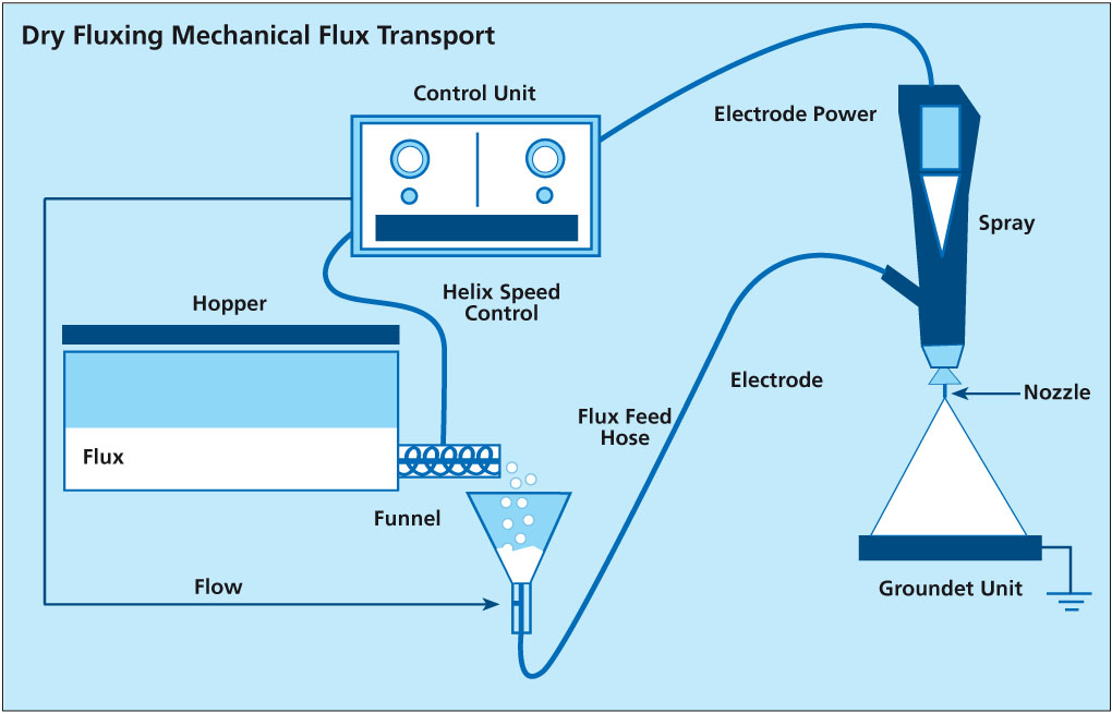
Dry Fluxing – Mechanical Flux Transport

The second type of powder feed system works on the principle of mechanical delivery or positive displacement. This means that the powder feed rate to the air pump is controlled by a screw or auger. The flux is contained in a main feed hopper and delivered mechanically at a controlled feed rate to the air pump. Powder flow is thus regulated by controlling the auger feed rate. This powder feed system does not rely on the flux being fluidized. Nonetheless, modifications over conventional mechanical powder feed systems are still necessary to overcome the differences between the flux characteristics and conventional powder paints.
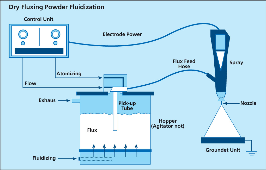
Dry Fluxing – Powder Fluidization

Japanese heat exchanger manufacturers have used the technique of dry fluxing for many years now. Within the last few years, North American and European manufacturers have also installed electrostatic fluxing stations. Experience with this technique is being accumulated at a rapid rate, given that the equipment manufacturers and flux suppliers are taking an active role in improving the technology.

Considerations
Fixtures are used to hold the braze assembly in place during brazing. Surfaces with molten filler metal are very “greasy” and the fixtures need to hold the shape and tolerances during heat-up. Fixtures may also be used to support attachments such as inlet or outlet tubes.
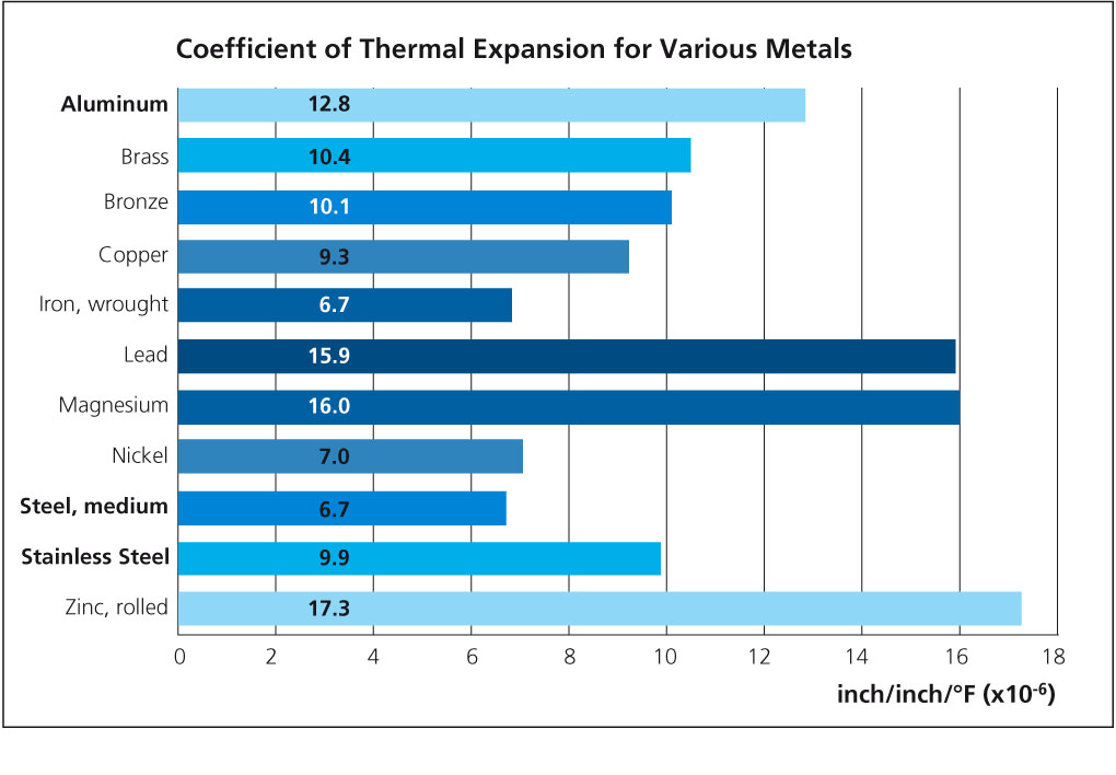
When considering the type or configuration of fixtures to use, there are a number of considerations to take into account. For example, differential expansion between fixture and braze assembly increases part compression significantly during heat-up. One must be acutely aware of the differences in the coefficients of thermal expansion between stainless steel and aluminum. Aluminum expands much faster than stainless steel and this must be taken into consideration when designing a fixture. This is important to prevent distortion of the heat exchanger at final brazing temperature.
It is also important to note that molten filler metal dissolves steel and stainless steel. It is important to minimize contact with filler metal. It is also possible for aluminum to braze to fixtures. It is therefore important to either use a brazing stop-off for surfaces in contact with aluminum or to oxidize the fixtures when new or after cleaning. This can be done simply by running the fixtures through the brazing furnace.

Permanent Fixtures
The most common type of fixtures for heat exchanger manufacturing are permanent fixtures, ones that are used over and over again. These are usually made and should be made from stainless steel to prevent rust contamination in the slurry tank. The preferred material for fixtures is AISI 309 or 316, but most stainless steel alloys are perfectly acceptable.
Springs may be used in the fixture to apply a certain “holding” pressure to the heat exchanger during brazing. However, the technique of using springs seems to be less common than in the past. More often now, fixtures are designed with fixed dimensions. The heat exchanger is compressed slightly and loaded into the fixture. When the source of compression is removed, the natural spring-back holds the heat exchanger in place against the fixture.

Cleaning
As flux builds up on permanent fixtures and may contaminate the flux slurry, it is necessary to routinely clean the fixtures to remove flux and other contaminants that may have accumulated. There is no convenient chemical cleaning method to remove flux residues. The most appropriate methods are by mechanical means such as wire brushing or grit-blasting.
Once the residues have been removed by one of the above methods, the fixtures should be oxidized by running them through the brazing furnace. Non-oxidized fixtures are likely to stick or even braze to the work piece.

Steel banding
An alternative to permanent fixtures is the use of disposable steel banding. Since mild steel can be used, material costs are kept to a minimum. Wax coated mild steel bands are often used to prevent the banding material from rusting that can contaminate the flux slurry and discolor the heat exchanger. The steel bands are used only once and are disposed of after brazing.
Steel banding requires experimentation to determine the appropriate tension and positioning. Thereafter, an automatic banding machine should be used to ensure consistency.

Sample Preparation – Orientation

The heat exchanger chosen for the purpose is a NOCOLOK Flux brazed radiator. To provide some orientation as to where the metallographic sections will be taken from, Figure 1 shows the water-side header area (top) and part of the finpack, sidesupport and header area.

Figure 1

In most metallographic investigations of brazed heat exchangers, the critical joints to examine are the tube-to-header joints and the fin-to-tube joints. For instance, a leak in a tube-to-header joint constitutes a failure. The fin-to-tube joint on the other hand, although not as critical as the tube-to-header joint, is the key area where heat transfer takes place. It is therefore necessary that the fin-to-tube joints are metallurgically bonded (i.e. brazed) for maximum heat transfer efficiency.

Sample Preparation – Sectioning

With a band saw, the radiator can be cut down through the center of the tubes (see Figure 2). This will keep the fins intact. If necessary, one can saw through the fins if the blade is kept as close to the outer tube wall as possible. That is the outer tube wall can be used to guide the saw blade. Otherwise, it is better to saw through the center of the tube where the inner walls will act as the guide.

Figure 2

Once the above sections have been obtained, the samples can be sawn longi-tudinally through the center of the tube and header as shown in Figure 2, right. The tube-to-header and tube-to-fin sections can then be cut. The size of the cut samples must fit inside a 30 mm or 40 mm mount.  Note that it is the cut face that will be grinded and polished.

Grinding and Polishing

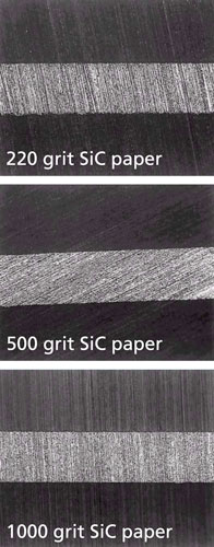
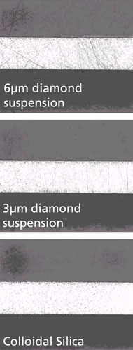
The following section shows what the sample actually looks like after each grinding and polishing step. The intention is to help the metallographer track the progress of grinding and polishing with the help of visual aids.

Figure 3 shows what a section of „unbrazed“ brazing sheet looks like under the microscope after wet grinding with 220, 500 and 1000 grit SiC paper. In each case, the sample is ground until all the grinding lines appear in the same direction, across the entire grinding face. It also helps that the grinding lines go in the direction of, or perpendicular to the area of interest. In this case, the grinding lines all run perpendicular to the braze sheet after 220 grit paper. After 500 grit paper (rotating the sample 90°), the grinding lines all run parallel to the tube and after 1000 grit, once more perpendicular to the braze sheet.

Figure 4 shows what the braze sheet looks like after each successive polishing step. After the 6 µm diamond suspension, the microstructure of the braze sheet becomes visible (more on microstructure later). At this stage, there are still a number of scratches. After the 3 µm diamond suspension, the micro-structure is clearer and there are less scratches.  Only after the colloidal silica are all scratches removed. The 64x magnification in Figure 4 is too small to reveal fine micro-structural details after the colloidal silica polish, but what is evident is that the braze sheet is now highly polished and scratch free.

Figure 3


Figure 4

How to obtain?

A lot of information can be gained from heat exchanger brazing cycle temperature profile. It is probably one of the most important pieces of information that the brazing engineer can use to fully understand his process. A temperature profile will provide information such as heating rate, maximum peak brazing temperature, time at temperature, temperature uniformity across the heat exchanger and cooling rate. No other tool can provide so much information.

The simplest method for obtaining a temperature profile is to attach thermocouple wires to various parts of the heat exchanger and graphing the resulting profile on a chart recorder. The disadvantage of this method is that the thermocouple wire must be long enough to traverse the length of the furnace. One must also ensure that the wire does not become entangled in the mesh belt.

The second and more common (also more expensive) method of obtaining temperature profiles is with the use of a thermally insulated data pack. The data pack is a stand-alone unit capable of withstanding brazing temperatures. The thermocouples wired into the data pack are attached to various parts of the heat exchanger. The data pack then travels on the belt with the heat exchanger through the brazing furnace. At the end of the run, the data stored in the data pack is downloaded into a computer where graphs can be generated. The sophisticated software allows the user to determine quickly a number of parameters such as maximum temperature reached by each thermocouple.

Recent advances in thermal profiling allows getting information in real time. The thermally insulated data pack transmits data in real time from inside the brazing furnace to a computer situated outside the furnace using the latest radio telemetry technology. Changes to the furnace settings can now be seen instantly1.

Heating Rate

A minimum average heating rate of 20°C/min up to the maximum brazing temperature is recommended. With very large heat exchangers such as charge air coolers, lower heating rates may be used, but with higher flux loadings. Once the flux starts to melt, it also begins to dry out. With slower heating rates, it is possible that the flux can be sufficiently dry as to loose its effectiveness when the filler metal starts to melt or before the maximum brazing temperature is reached.

Heating rates up to 45°C/min in the range of 400°C to 600°C are not uncommon. One could say that the faster the heating the better. However, temperature uniformity across the heat exchanger must be maintained especially when approaching the maximum brazing temperature and this becomes increasingly more difficult with fast heating rates.

Maximum Brazing Temperature

For most alloy packages, the recommended maximum peak brazing temperature is anywhere from 595°C to 605°C and in most cases around 600°C.

Temperature Uniformity

During heat up, there may be quite a variation in temperature across the heat exchanger. The variation will tighten as the maximum temperature is reached. At brazing temperature it is recommended that the variation should not exceed ± 5°C. This can be difficult to maintain when larger units are processed which have differing mass areas within the product.

Time at Temperature

The brazed product should not remain at the maximum brazing temperature for any longer than 3 to 5 minutes. The reason is that a phenomenon known as filler metal erosion (core alloy dissolution / Silicon penetration into the base material) begins to take place as soon as the filler metal becomes molten. And so the longer the filler metal remains molten, the more severe the erosion is.

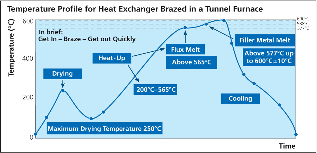
The graph below shows an actual temperature profile for a heat exchanger brazed in a tunnel furnace. One characteristic feature of all temperature profiles is where the curve flattens out when approaching the maximum peak brazing temperature (area shown in blue circle). The plateau in the temperature profile is associated with the start of melting of the filler metal at 577°C, known as the latent heat of fusion. It is called latent heat because there is no temperature change when going from solid to liquid, only a phase change.

Temperature profile for a heat exchanger brazed in a tunnel furnace.

1 D. Plester, Datapak Ltd., International Congress Aluminium Brazing, Düsseldorf (2002)

Process related causes

The service life of a heat exchanger may be shortened due to corrosion caused by process related events. Some examples are listed below:

Excessively high brazing temperature or too long time at temperature will lead to excessive Si diffusion in the core. Si diffuses along grain boundaries and this can increase the susceptibility to intergranular corrosion. By maintaining proper time-temperature cycles and thereby minimizing Si diffusion, intergranular attack can also be minimized.

Copper in contact with aluminum will cause a corrosion related failure very quickly. Copper is noble (cathodic) to aluminum and when these two metals are in contact in the presence of an electrolyte, the aluminum will be consumed rapidly. This may occur in a heat exchanger manufacturing facility where both Al and Cu heat exchangers are produced and there is cross-contamination of process routes. It only takes one small Cu chip to land on the surface of Al during some part of the manufacturing process to cause a short-term failure in the Al heat exchanger. If both Al and Cu heat exchangers are to manufactured under the same roof, it is recommended (and practiced) to physically separate the two production routes with a wall and take extensive steps to avoid cross-contamination.

Carbonaceous residues can be generated on the heat exchanger surfaces during the heat cycle from residual lubricants, excessive use of surfactants, binders in flux or braze pastes etc. Carbon plays very much the same role as Cu in that it is noble to Al. In a corrosive environment, carbon residues act as a cathode and Al as an anode, leading to the galvanic corrosion of Al. The best preventative measure is to ensure that the heat exchangers are thoroughly and properly cleaned and degreased prior to brazing. This includes monitoring the flux slurry bath for any signs of organic contamination (for instance oil slicks).

Coatings

Painting a heat exchanger offers some level of corrosion protection, but is primarily used for cosmetic purposes. Painting will enhance corrosion protection if it covers the entire heat exchanger uniformly and is free from defects. In fact, paint defects or stone chips will accelerate corrosion locally. Many Al producers believe it is better to leave the heat exchanger unpainted to prolong its service life.

Conversion coatings such as chromate or phosphate conversion coatings work differently than painted surfaces. Conversion coatings enhance the natural oxide film on Al, essentially making it thicker and more resistant to hydrolysis. These types of coatings are most often used with automotive evaporators.

Very often, heat exchanger manufacturers increase the flux loading on components to be brazed to compensate for furnace atmosphere or other process related deficiencies. The flux is an excellent “band-aid” and can be used as such, but only while the true problems are located and rectified. Long term use of higher than recommended flux loads can lead to other problems.

Over fluxing causes more KAlF4 evaporation and condensation. This will load up the dry scrubber more quickly. White powder will accumulate more quickly on the curtains at the exit end of the furnace. If this is noticed, there is a very good chance that the dry scrubber is loading up more quickly.

There will be a more rapid build-up of the flux inside the furnace. This is a common issue with over fluxing whereby flux builds up on the muffle floor at the entrance to the cooling zone where it will solidify. This flux build up has been known to deflect the mesh belt.

There is more rapid build up of the flux on the fixtures which can significantly reduce maintenance intervals.

Over-fluxing can lead to visible flux residue on the brazed heat exchanger which may increase the incidence of flux residue fall-off. Excess flux residue dulls the appearance of a brazed heat exchanger and can also accumulate in the gasket areas causing problems with seals. Too much flux residue will also inhibit surface treatments such as painting or conversion treatments.

This increase in efficiency means the same refrigerant capacity can be produced with smaller exchange surfaces at the condenser and evaporator, with an associated reduction in piping volume, i.e. a higher heat exchange efficiency means smaller systems and lower refrigerant charge. Important given that third generation HFC refrigerant blends such as R 410 A are much more expensive than R 22 which they are now replacing.

Greater reliability, easy recycling and lower weight Aluminum alloys offer high heat conductivity but also high resistance to corrosion. Brazed heat exchangers also boast higher mechanical resistance, especially in the fin connection, so that even incorrect handling or accidental collisions cause less deterioration with time. Moreover, microchannel heat exchangers are single-alloy system components which means easy and efficient recycling. And, although aluminum brazed heat exchangers have a similar performance to all copper units of similar size, they are about three times lighter.

Yorck heat exchanger

How to measure?

In the case of heat exchangers, the surface area being fluxed must first be determined. For ease of calculation, the louvers on the fin can be ignored. The radius on the fin can also be ignored.

Imagine then the fin pulled out of the heat exchanger and straightened out to form one long strip. Similarly, the surface area of the slots in the header can also be ignored.

Remember that in calculating the surface area of the heat exchanger, there are 2 sides to every tube, 2 sides to every fin and 2 sides to the headers. The total surface area is then expressed in m2: All dimensions are in meters (m) to yield a surface area in square meters.

Header


Assuming it is a cylindrical (condenser) header:

SA (m2) = (2 x 3.14 x radius of header(m)) x length of header (m) x 2 headers

Assuming it is a radiator header:

SA (m2) = length of header (m) x width of header (m) x 2 (sides/header) x 2 (headers)

Tubes

SA(m2) = width of tube(m) x length of tube (m) x 2 (sides/tube) x total number of tubes

Fins

Ignore the louvers in the fins

SA (m2) = width of fin (m) x (fin height (m) x number of fin legs/tube) x 2 ( sides/fin) x total number of fins

Total Surface area in m2 = SA headers + SA tubes + SA fins

To determine the flux loading, a degreased and thoroughly dry heat exchanger is weighed. The heat exchanger is then run through the fluxer, blow-off and dry-off section of the furnace. The heat exchanger is removed just prior to entering the brazing furnace and weighed again.

The flux coating weight is then determined using the following formula:

Weight of unit fluxed and dried (g) – weight of unit un-fluxed (g) x Surface area (m2)

To make sure that the flux loading was determined on a completely dry unit, run it through the dry-off section a second time and re-weigh.

See also: Flux loading

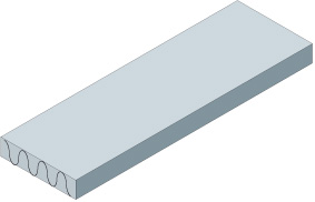
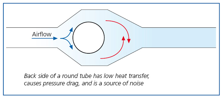
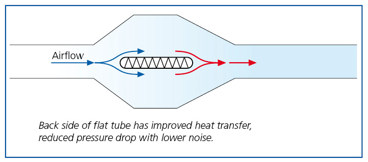
Brazing also offers the chance to change the design of heat exchangers by substituting round tubes with flat channels (microchannels) which offer improved heat transfer on both refrigerant and air sides for two reasons: better section/surface ratios, which affect the efficiency of heat exchange on the air and the refrigerant side; smaller surfaces in the air stream shadow where heat transfer is inefficient and lots of noise is generated. Brazed connections between fins and tubes are also rigid structures producing less mechanical noise in the presence of air turbulence.
More efficient heat exchange means lower air flows to exchange the desired heat, and microchannel technology already offers lower resistance to the air flow – flat is therefore better than round: reducing resistance by up to a factor of 3 under typical operating conditions (see figures below)!

Round Tubes – Air-Side Effects

Round Tubes – Air-Side Effects

Flat Tubes – Air-Side Effects

Flat Tubes – Air-Side Effects

One of the largest potentials to increase efficiency of heat exchangers lies within the heat-transfers: reducing condensing temperatures by 3 °K will improve overall system efficiency by approx. 10 % for a standard R 410 A air conditioning cycle. A minimization of the temperature difference between the air flows and the phase change temperatures of the refrigerants can be achieved by improving the heat transfer efficiency of the heat exchangers. Brazed microchannel heat exchangers have already proven that they are a cost effective solution for the utilization of this optimization potential – as well as boasting a number of other benefits (see below). Brazed microchannel heat exchangers have been the technology of choice in the automotive industry for the past 10 to 15 years, and are already making inroads into the stationary HVAC&R industry for the following convincing reasons.

Poor contacts between fins and tubes account for approximately 5 – 10 % of heat transfer resistance in a standard heat exchanger manufactured by mechanical or hydraulic expansion of the round tubes because this always leaves imperfect connections between the parts. The microscopic image shows the small gaps between fins and tubes responsible for contact resistance that reduces heat transfer performance.

Heat transfer

Fig. 1: Small gaps between fins and tubes reduce heat transfer performance in mechanically or hydraulically manufactured heat exchangers.

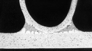
Brazed connections are much better because they metallurgically bond the fins and tubes in a single conductive material, eliminating all potential sources of contact resistance.

Heat transfer 2

Fig. 2 Excellant heat transfer performance because no gaps in brazed connections.