Selective Pre-Fluxing with Adhesives – Fashion or Progress

Summary

Over the last 15 years, selective prefluxing – also called paint fluxing or binderbased fluxing – has evolved as an alternative method for applying flux powder in the aluminium brazing industry. There are many activities to define process parameters of fluxing with adhesives.

The first part of this paper outlines key features of prefluxing. The methodology for measurements of physical characteristics of binders and paint flux mixtures are described. General rules for behaviour of flux paints in brazing process are discussed together with some examples of flux paint features.

In the second part a case study is shown to illustrate common challenges when brazing with flux paint. The third and last part of this paper provides a cost comparison as guidance for choosing the right fluxing method for two different cases, one being extremely negative and the second as a positive case.

4. Flux Paint Risk Point

The fundamental condition for successful brazing is having a substrate surface which is well wetted by a molten filler alloy. Any binder as an organic compound contains carbon. This carbon must be removed before brazing, otherwise it will form a very thin deposit on the substrate surface preventing wetting by the molten filler alloy2. When the flux paint is deposited on open surface areas, like for example on the radiator headers, there is no issue to remove the binder by evaporation at higher temperature. However, when the flux paint is applied in enclosed spaces, like for example on inner surfaces of condenser manifolds, the removal of binder becomes challenging. Proper de-bindering conditions must allow the binder fumes to escape completely. Residual binder – like any other trace organic – carbonizes during the brazing cycle – causing surface discoloration and potentially poor brazing.

Fig. 5 shows a leak in the tube apex. The condenser manifold was made of two halves: cover and header. Only the cover part was prefluxed by immersion. Composition of the flux paint: flux ~ 30%; carrier (acetone) ~ 62%; binder (polymethyl methacrylate) ~ 12%.
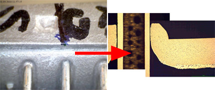
Fig. 5: Leak in tube to manifold joint in condenser with manifold half flux painted by immersion.

The gap size between the tube and manifold is in the range of 40µm, which is well within the maximum recommended tolerance.
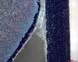
Fig. 6: Dark field image of the non brazed tube to manifold joint.

Dark field image of the non brazed joint showed that the gap is filled with transparent substance. Investigation by Scanning Electron Microscope revealed that the joint was completely filled with post braze flux residue.
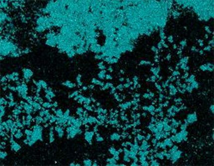
Fig. 7: Mapping of potassium in the non brazed area of the joint.

The tube surface presented in Fig. 7 shows very uneven flux distribution. There are areas completely free of potassium (flux) and areas covered with a layer of flux. This would indicate that the tube surface was not completely wetted by flux upon application. Such “poisoning” of the surface can appear when it is contaminated with carbon. Though the overall level of carbon (as examined be SEM) is low, its distribution is uniform. The carbon most likely originated from binder traces. It seems that during debindering treatment the carbon got embedded into the aluminium oxide layer. Such a modified aluminium oxide layer is more difficult for the flux to remove.

5. Example of cost comparison calculation

The major reason behind the decision to introduce flux painting technology should be reduced overall cost of the manufacturing process. These should include:

  • Media
  • Maintenance
  • Environment (cost of waste utilization)
  • Raw material and consumables
  • Labor
  • Investment cost (depreciation)

In the following section we will present two examples of such calculations. It must be pointed out that the quoted numbers, though not far away from the values one can see in an aluminum brazing factory, may always differ from case to case. Thus the presented calculations should be considered only as a tool in which individual data needs to be fed, not as an indication which fluxing method is better.

Case A: Condensers

In the modified condenser production, the tube to fin joints are realized by tube precoating with NOCOLOK Si Flux3 – while the manifolds are prefluxed with a water based flux paint. This concept allows for complete elimination of the fluxer and the thermal degreaser from the brazing line. The dryer then acts as preheat and oven, where partial debindering takes place.
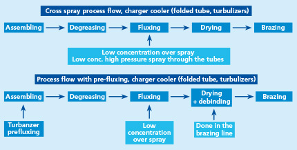
Fig. 8: Standard and modified process flow for condenser production.

Table 3 shows assumed input values like for example cost of electricity and the difference between the cost of standard process and modified one in the above listed categories. The whole calculation is done in an excel table where one can play with different input data which shows how sensitive the overall cost is to a change in a given parameter. In this case analyses showed that the most sensitive factor is the cost of the Sil Flux precoated tubes. Change of price in tube material by 10% can entirely reverse the final result.
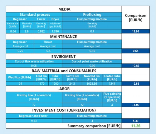
Table 3: Example calculation for standard and modified condenser manufacturing. Production level 200 pcs/hour.

Case B: Charger Coolers

Charge Air Coolers have one characteristic feature. Inside the tubes there are turbulators to make the flow of the hot compressed air more turbulent to increase the transfer of heat from the air to the tube walls. A condition to secure sufficient tube resistance to the inner pressure is to have all turbulators uniformly brazed to the inner tube surface. This requires fluxing of the tube’s internal surface. The most robust method is fluxing by immersion. This however produces higher post brazed flux residue levels and it is usually a bottle neck in the continuous production flow.

The other method is to apply a high pressure spray of flux slurry across the tubes. When combined with cross blow of high pressure air it secures proper inner fluxing even up to 900mm long tubes. This method does not slow down the production flow in a continuous line. For comparison the latter cross spray fluxing method is compared with prefluxing of turbulators. It should be remembered that wet fluxing is applied on tube to fin joints in both cases.
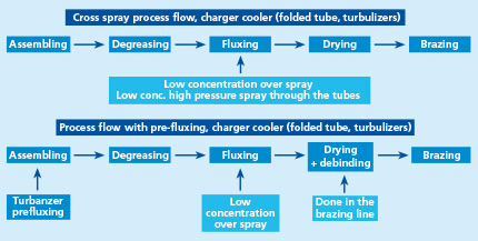
Fig. 9: Standard and modified process flow for charger coolers production.
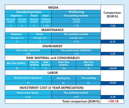
 

Table 4: Example calculation for standard and modified charge air cooler manufacturing. Production level 200 pcs/hour.

In this example there is no major change in the brazing line and as a matter of fact an additional entirely separate operation is added. This situation is somewhat improved when the flux painting process of the turbulators is incorporated into the tube making unit; however it eliminates only the negative effect of additional labor. The major cost is connected with consumption of flux paint. On average the cost of flux paint is about 20% higher than the cost of flux. Assuming liquid flux paint consumption of 4 grams per one turbulator and 50 grams of flux powder used on one charge air cooler fluxed by cross spray we will end up with such high difference in cost. In spite of this fact there are production lines which use the flux painting applied on turbulators.

6. Summary and conclusions

During recent years, the concept of prefluxing with binder flux/ paint flux has become quite popular as a method for fluxing. However when taking a decision about choosing this technology, the following aspects should be considered:

  • What level of adhesion is required?
  • Are we going to deal with binder removal from enclosed spaces?
  • Is the binder vapor going to affect my equipment?

and the most important one:

  • will there be real cost benefits?

In the case of cost calculations for NOCOLOK Sil Flux coated extruded condenser tubes the major factor influencing the overall cost is the cost of the coated tubes. Though the presented calculation is only an example and can slightly vary from case to case, it is the authors‘ opinion that in certain cases the introduction of this technology can be justified by cost savings. In the case of flux painted turbulators for charge air coolers, the major factor influencing the overall calculation is the cost of flux paint. It seems that such process is not always justified from the cost point of view.

7. References / Literature

1 Swidersky, H. W., Aluminum Brazing with Non-Corrosive Fluxes – State of the Art and Trends in NOCOLOK Flux Technology, Tagungsband, Hochtemperaturlöten und Diffusionschweißen, DVS-Berichte Bd. 212, Düsseldorf: DVS-Verlag, pp. 164-169, 2001

2 Hawksworth, D. K., A Study of Organic Residues on the Surface of Vacuum Brazing Sheet, 2nd International Congress Aluminium Brazing, Düsseldorf 2002, conference proceedings

3 NOCOLOK Sil Flux: fine grade and extra fine grade
Selective Pre-Fluxing with Adhesives – Fashion or Progress

Summary

Over the last 15 years, selective pre-fluxing – also called paint fluxing or binder-based fluxing – has evolved as an alternative method for applying flux powder in aluminium brazing industry. There are many activities to define process parameters of fluxing with adhesives.

The first part of this paper outlines key features of pre-fluxing. The methodology for measurements of physical characteristics of binders and paint flux mixtures are described. General rules for behaviour of flux paints in brazing process are discussed together with some examples of flux paint features.

In the second part a case study is shown to illustrate common challenges when brazing with flux paint. The last part of this paper provides a cost comparison as guidance for choosing the right fluxing method for two different cases, one being extremely negative and the second as a positive case.

3. Overview of Binders

Group Adhesion providing components Co-solvents / dispersion agents (examples only) Carriers / solvents
1 Polyurethane (aqueous polyurethane dispersion) N-Methyl-2-pyrrolidon water
2 Water-based acrylic 3-Methoxy-3-methyl-1-butanol water
3 Solvent-based acrylic 1-Methoxy-2-propyl acetate and others Preferably non-explosive and non-flammable organic solvents (e.g. esters of dicarboxylic acids)

Table 1: Main groups of flux binders / flux paints.

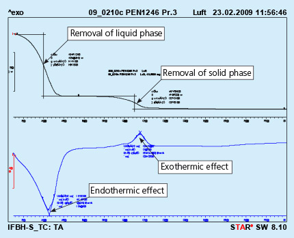
One of the most important characteristic of a binder is the kinetics of binder removal. This property is measured by a method called Differential Thermal Analysis [DTA]. The specimen (binder or flux paint) is placed in a small crucible and heated with a preset rate. The device measures the change of weight of the specimen and heat emitted or absorbed by the sample. The test can be done in air or at a chosen gas atmosphere.

An example of the curves obtained in such device is shown in Fig. 1

Fig. 1: DTA curves obtained from solid flux paint sample. Test performed in air. 

The upper curve represents lost of weight upon heating, and the lower curve represents thermal effects appearing in the heated sample. The endothermic effect is associated with evaporation of the sample and the exothermic effect is usually connected with burning of the sample.

It should be observed that the above curves represent a sample of liquid flux paint. The removal of the the liquid phase (carrier evaporation) takes place during curing of the painted part. This process is always done before putting the parts into the brazing line. For flux paints made with water as a carrier it is simple evaporation.

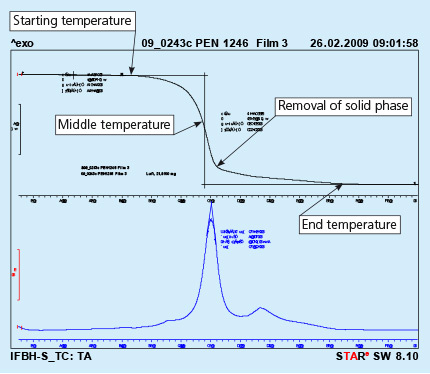
Removal of the solid phase (cured binder) takes place at much higher temperature then evaporation of the carrier. It usually happens in the brazing line – in the dryer and partially in the brazer. Kinetics of the solid phase removal is shown in Fig. 2. In this case the analyzed sample is prepared by painting a metal surface, curing the paint and careful scratching off the solid paint, which is then analyzed in DTA device.

Fig. 2: DTA curves obtained from liquid flux paint sample. Test performed in air. 

As can be seen the end of the binder removal is in the temperature range of 450oC. The above presented curves show the removal of binder at a constant heating rate of the sample (in this case 10oC/min). In the brazing line the prefluxed parts firstly go through a dryer where the temperature for dry parts is usually in between 200oC to 250oC. The parts for a continuous brazing line usually stay in the dryer no longer than 10 minutes.

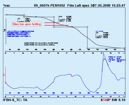
To simulate this condition, a dry flux paint sample was analyzed by DTA with a hold for 10 minutes at 300oC. As can be seen from Fig. 3, holding at constant temperature for a prolonged time does not lead to full removal of the binder. In the given case only about 36% of the binder was removed.

 Fig. 3: DTA curves with holding time 10min. at 300oC Test performed in air.

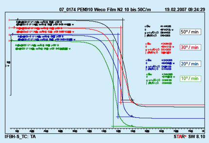
Different furnace design and different size of the brazed parts are responsible for different heating kinetics in the brazing lines. An influence of different heating rates on kinetics of binder removal is shown in Fig. 4.

Fig. 4: DTA curves with different heating rates Test performed in nitrogen. 

The curves presented in Fig. 4 were obtained from analyzing a polyurethane binder heated in nitrogen atmosphere. It can be seen that only the middle temperature is moved to higher values with increased heating rate. The beginning and end of the debinding process do not depend on the heating rate.

Several examples of debinding temperatures for different type of binders are presented in table 2.

Binder Type Tested in Air Tested in Nitrogen
Middle temp. [°C] End Temp. [°C] Weight loss [%] Middle temp. [°C] End Temp. [°C] Weight loss [%]
Polyurethane Binder A 355 530 99.7 370 460 99.6
Polyurethane Binder B 360 550 98.5 370 460 97.5
Acrylic Binder C (water soluble) 317, 382 450 87.2 220, 387 430 85.2
Acrylic Binder D (high adhesion) 267 420 Not measured* 385 Not measured* 27.5
Acrylic resin Binder E 275 400 86.9** 370 450 89.3**
* DTA performed only on ready mixtures
**Lower values due to some flux residue (sample obtained from ready mixture)

Table 2: Examples of debinding temperatures for different types of binders.

Will be continued soon.

Selective Pre-Fluxing with Adhesives – Fashion or Progress

Summary

Over the last 15 years, selective pre-fluxing – also called paint fluxing or binder-based fluxing – has evolved as an alternative method for applying flux powder in aluminium brazing industry. There are many activities to define process parameters of fluxing with adhesives.

The first part of this paper outlines key features of pre-fluxing. The methodology for measurements of physical characteristics of binders and paint flux mixtures are described. General rules for behaviour of flux paints in brazing process are discussed together with some examples of flux paint features.

In the second part a case study is shown to illustrate common challenges when brazing with flux paint. The last part of this paper provides a cost comparison as guidance for choosing the right fluxing method for two different cases, one being extremely negative and the second as a positive case.

1. Introduction

In aluminium brazing industry fluxing is one of the most important steps in the production process. Flux water slurry application is considered as a standard and as a matter of fact very robust methodi. We believe that about 70% of overall fluxing activities are done by flux water slurry spray. This method has however certain disadvantages like troublesome slurry preparation and requirements for large and sometimes expensive machinery.

In order to lower production costs, new fluxing technologies have been introduced. One of them is called paint fluxing or binder-based fluxing which allows for elimination of wet fluxing process from the brazing line. Actually, the prefluxing process can be even done by an external company/subcontractor. It is nevertheless still a process of coating, which is done to particular component surfaces of the whole assembly – usually before the components are assembled.

In the industrial practise – particularly when one is in contact with many different users of the prefluxing technology – it is quite important to define the basic features and properties of discussed technology.

Flux Painting Booth

Flux Paint:
A mixture of brazing flux with binder, demineralised water or organic solvent, and thickener (the latter not always obligatory)

Binder:
Organic complex compounds, which are activated by curing – to provide adhesion of flux particles to the painted surface.

Thickener:
Organic substance, which is used to adjust viscosity and to facilitate re/mixing of the flux paint.

Curing:
Drying of the painted parts – usually with a blow of hot air (about 150°C). During that process liquid carrier (water or organic solvent) is evaporated and binder becomes activated to provide adhesion.

Adhesion:
Qualitative or quantitative measure by which strength of the flux particles bonding to the painted surface is determined. There are many different methods to describe adhesion of the flux paint. At Solvay we are using a simple quantitative method: A coated and cured coupon is placed in a holder positioned on a scale, a steel wedge is moved along the coupon with a gradual pressure increase. The weight at which the first scratches appear is a numerical value for adhesion.

Debinding:
Removal process of the binder from the painted surface done by treatment with high temperature, either in air or in ambient atmosphere.

Binder must be removed before reaching brazing temperature; otherwise the carbon residue will interfere with the brazing process – leaving both black stains on the part surfaces and very often leading to lack of brazing. Removal of the binder is done by applying high temperature to the assembled parts. In most cases the process of binder removal is realized in the brazing line both in the dryer and brazer.

2. Basic Rules for Flux Painting

The process of coating can be done by spraying, roller coating, brushing, or dipping. Uniformity of coating is very important, any agglomerates and lumps must be avoided. The flux paint can be prepared without thickener. Practically it is required in the mixture when a longer storage is expected (i.e. more then few days). There is an optimal temperature for curing resulting in maximum adhesion. Curing at ambient temperature is possible, but it will yield lower adhesion. Curing at too high temperature can lead to significant loss of adhesion.

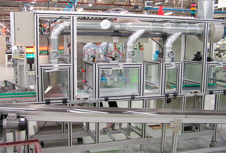
Apart from the curing condition, adhesion also depends on the ratio of binder in the mixture (the more binder in the mixture the stronger adhesion), and the type of the binder (as a rule of thumb: the higher flash point of the binder the stronger adhesion). The most common method for prefluxing with binder mixture is using an atomized spray method on a machine which performs degreasing, painting and curing.

Will be continued soon.

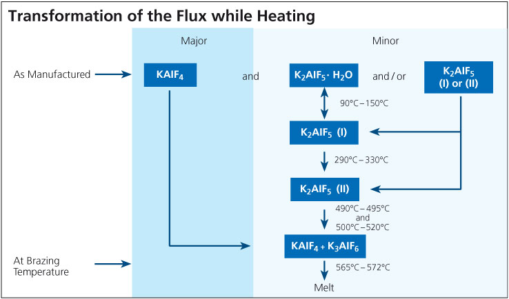
As manufactured, a non-corrosvie K-Al-F-type flux typically is a mixture of potassium tetra-fluoroaluminate (KAlF4), and also contains potassium penta-fluoroaluminate (K2AlF5). K2AlF5 exists in different modifications: potassium penta-fluoroaluminate hydrate (K2AlF5 · H2O), and hydrate-free (K2AlF5).
During the brazing process, the material undergoes essential physico-chemical alterations. While the chief component, KAlF4, is simply heated up, the compound K2AlF5 · H2O begins to lose its crystal water from 90°C (195°F) on. When the temperature is further increased within the ranges of 90° – 150°C (195°F – 302°F), and 290°C – 330°C (554°F – 626°F), two different crystallographic (structural) modifications of K2AlF5 are formatted.

When the furnace temperature is raised above 490°C (914°F), K2AlF5 begins to react chemically. According to the equation:

2 K2AlF5 → KAlF4 + K3AlF6 (Equation 1)

the exact amount of potassium hexa-fluoroaluminate (K3AlF6) necessary for a eutectic flux composition (i.e. mixture of two or more substances which has the lowest melting point; see phase diagram) is obtained from the original K2AlF5 content. At brazing temperature, the resulting flux composition has a clearly defined melting range of 565°C to 572°C (1049°F – 1062°F). The flux melts to a colorless liquid.
Due to a vapor pressure of 0.06 mbar at 600°C, some of the KAlF4 evaporates during the brazing cycle, particularly once melting temperature is reached. The total content of KAlF4 contained in the exhaust is depending on time and temperature. Based on results from TGA analysis (with a heating rate of 20°C/min), the quantity of volatile compounds in Flux between 250°C and 550°C (482°F and 1022°F) is approximately 0.2 to 0.5%. These flux fumes contain fluorides and have the potential to react with the furnace atmosphere, especially moisture, to form hydrogen fluoride according to the equation:

3 KAlF4 + 3 H2O → K3AlF6 + Al2O3 + 6 HF (Equation 2)

This is one of the reasons, why the brazing process should take place in a controlled atmosphere (nitrogen) with low dew point and low oxygen level (another reason is to minimize re-oxidization effects on the aluminum surfaces).

Directly after brazing has been completed, flux residues consist mainly of KAlF4 and K3AlF6. In the presence of moisture from the surrounding atmosphere, the K3AlF6 is converted back to K2AlF5 · H2O over time (several days) in a reaction reverse to the one described in equation 1 followed by a re-hydration step.

The schematic below illustrates the transformations that occur as the flux is heated to brazing temperature. Note that these phases are unstable outside the furnace atmosphere.

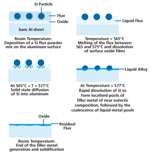
NOCOLOK® Sil Flux brazing is a technique, which eliminates the need for clad brazing sheet or conventional Al-Si filler metal. Sil flux brazing uses filler metal generated in-situ to effect brazing. The mechanism for creating this filler metal in-situ is described below:

  1. One of the surfaces to be joined is coated with a mixture of NOCOLOK® Flux and metallic Si powder. The coated assembly is then heated in the same fashion as in conventional furnace or flame brazing techniques.
  2. As the temperature rises, the flux melts at 565°C, dissolving the oxides on both the Al substrates and the Si particles.
  3. The bare Al surface is now in contact with metallic Si, and in the absence of oxides, allows solid-state inter-diffusion of Al and Si. Very quickly the composition near a Si particle reaches that of the Al-Si eutectic (Al-12.6% Si).
  4. As the temperature increases beyond the eutectic reaction temperature of 577°C, the formation of a liquid pool is established. The formation of the liquid leads to rapid dissolution of the remaining Si through liquid diffusion. The pool of liquid continues to grow, consuming Al, until all of the Si is consumed in the melt. In the presence of a joint, the liquid pool is drawn to the joint by capillary action.
  5. Upon cooling, the liquid layer solidifies to form a metallurgical bond between the components.

Sil Flux Process

When brazing aluminum to stainless steel using:
a) NOCOLOK® Flux and Al-Si filler alloys are suitable
or
b) alternatively CsAlF-Complex flux (melting range between 420 and 480°C) and Zn-Al filler alloys.

Regarding a): Brazing of aluminum to stainless steel works both with NOCOLOK® Flux + Al-Si filler alloy and with NOCOLOK® Sil Flux. After the flux melts and the oxides are removed, there is a reaction between Al and Fe, forming a thin intermetallic layer of FeAl3. This layer forms the metallurgical bond between the Fe and Al components. FeAl3 is very brittle and thus the thickness of this layer should be minimized, otherwise the joint can easily fracture.

From a metallurgraphic point of view, there is a multi-layer system (microscopic structures). First, there is the stainless steel, then the layer of FeAl3, then the Al/Si filler metal, and finally the aluminum base material. The thickness of the brittle FeAl3 layer is a function of brazing time and temperature; – consequently the need for a short brazing cycle with fast heat-up and very short holding time at maximum temperature. Too high brazing temperatures must be strictly avoided. Only with a short brazing cycle, successful joining of aluminum to steel is possible.

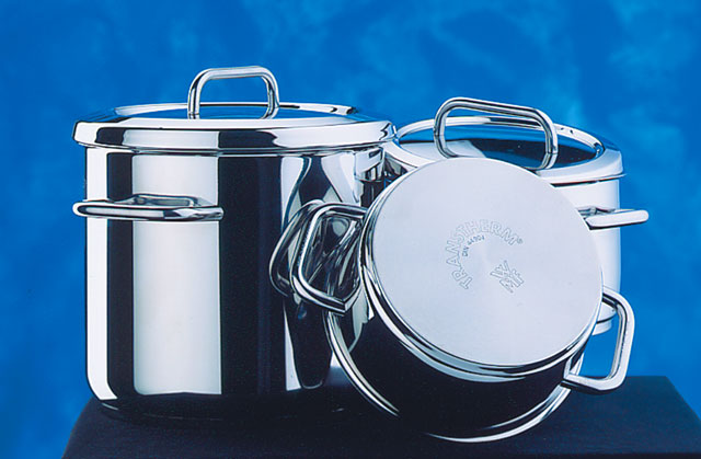
Joining of Al to steel using NOCOLOK® Flux is done on large scale commercially for the production of pots and pans (stainless steel pots with aluminum ‚compensation base plates‘) – mostly in induction brazing. It is also used for the production of heating elements (steel heating plates with aluminum base plates and tubes for the electrical heating wires). Another application for aluminum to steel joining is brazing of large aluminum-plated steel tubes – up to 11 meters long – with aluminum fins for power plant cooling modules.

In the manufacturing of pots and pans where there is a large surface area between the Al base plate and the pot, a mixture of filler metal powder and flux is often used. This circumvents the use of filler metal shim stock which is said to be costly and difficult to implement. In Al tube to steel or stainless steel tube joining, conventional flame brazing techniques can be used. Filler metal wire, either pre-placed or fed into the joint must be used. In the production of power plant cooling modules (with aluminum-plated steel tubes), the filler alloy is provided by clad fin material.

The following article provides some answers on general questions regarding the use of NOCOLOK Sil Flux for manufacturing pots and pans.

What is the NOCOLOK Sil Flux quantity (per m²) required for sandwich brazing or pressure cookers (stainless steel to aluminium)?
The recommended load for NOCOLOK Sil Flux is approximately 15 to 25 g/m². Brazing aluminium to stainless steel requires rapid processing, i.e. very fast heating ramp and short time at brazing temperature. Usually, this can only be accomplished with induction brazing.

When brazing aluminium to stainless steel using NOCOLOK Sil Flux, the Sil Flux first forms the filler metal from the aluminium component. The filler metal then reacts with the stainless steel to form a thin layer of FeAl3.

From a metallurgraphic point of view, there is a multi-layer system (microscopic structures). First, there is the stainless steel, then the layer of FeAl3, then the Al/Si filler metal, and finally the aluminium substrate. The FeAl3 layer is very brittle, and so it is important that this layer is kept as thin as possible. The thickness of this layer is a function of time and temperature,- consequently the need for a short brazing cycle.

Brazing of Stainless Steel with Aluminium

To prepare a NOCOLOK Sil Flux slurry or paste: What is the exact mixing ratio (flux to solvent) required?
The mixing ratio for NOCOLOK Sil Flux slurries or pasts depends on the application method on site. In some cases, the main focus is a specific viscosity for an automated fluxing system. In other cases, only small flux quantities are prepared for immediate consumption.

NOCOLOK Sil Flux can be prepared with alcohol (ethanol or isopropyl alcohol) or alcohol/ water mixtures (70% alcohol content) in any ratio from 20 to 60 wt% (solids). As mentioned earlier, the actual slurry concentration will depend on the application procedure. The objective is to achieve 15 to 25 g/m² surface area.

If the NOCOLOK Sil Flux slurry is not completely consumed within one or two days, we recommend using pure alcohol as carrier to avoid any chemical reaction between the solvent and the metal powder (silicon). Due to hydrolysis of the silicon powder, water should not be used to prepare NOCOLOK Sil Flux paste.

Brushing, dipping or spraying can be utilised to apply the flux. Uniformity of the applied flux coating is very important.

How fast after applying NOCOLOK Sil Flux, the components should be processed for best results?
Before the part is heated up, the NOCOLOK Sil Flux slurry or past coating on the component surfaces should be thoroughly dried or allowed to evaporate. If alcohol is used as a carrier, the evaporation will only take a few seconds (with 15 to 25 g/m² flux load). NOCOLOK Sil Flux is non hygroscopic (i.e. the flux does not attract and absorb moisture) and non-corrosive (i.e. there is no reaction between the flux and the metal surfaces at room temperature). If a water mixture is used as the flux carrier, the components must be dried after flux application to avoid water-based corrosion effects.

What is the grain/ particle size distribution of the silicon metal powder in NOCOLOK Sil Flux?

The silicon particles in NOCOLOK Sil Flux show a particle size distribution curve with most of the grains within a range of 10 to 45μm. The Solvay specification for NOCOLOK Sil Flux (fine grade) – which is used for brazing pots and pans – is as follows:
< 5μm: < 25%
10 to 20μm: 50%
> 35μm: < 10%
> 74μm: not detectable (by laser particle size analysis)

What are the key points regarding product fit-up for good joint formation in NOCOLOK Sil Flux technology?

During the brazing process it is important that the components to be joined are in intermediate contact with each other. There must be firm pressure applied on all the surfaces of the plates throughout the brazing cycle to avoid large voids and gaps. Filler metal can only fill gaps up to a certain width (i.e. approximately 0.10 to 0.15 mm).

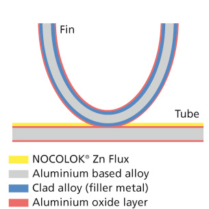
All heat exchanger manufacturers currently using zinc-coated tubes or zinc-coated brazing sheet and extrusions for corrosion protection are invited to consider NOCOLOK® Zn Flux as an alternative.

How does NOCOLOK® Zn Flux work?
The flux – a fine white powder with the chemical formula KZnF3 – is manufactured by Solvay Fluor similarly to standard NOCOLOK® Flux in a water-based batch process. Thus this material has a distinguished and uniquely homogeneous composition. Coating methods for the new product include slurry-based spraying, dipping, and painting, or electrostatic spraying for aluminium surfaces where zinc diffusion layers are required.

Zn Flux Before Brazing

Before Brazing

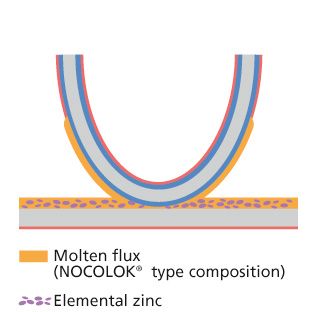
NOCOLOK® Zn Flux is a so-called “reactive” flux, i.e. the compound becomes active only at brazing temperature when it is in contact with aluminium. Pure KZnF3 without contact to aluminium decomposes at temperatures above 700°C. But when in contact with an aluminium substrate, this material initiates a series of reactions beginning at around 565°C. At first, a NOCOLOK®-type flux is liberated together with elemental zinc from the KZnF3 and the aluminium surface according to the following equation:

6 KZnF3 + 4 Al 3 KAlF4 + K3AlF6 + 6 Zn

The flux then dissolves the oxides present on the aluminium.

Zn Flux During Brazing

During Brazing (before filler metal melting)

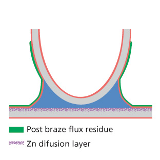
Once the Al/Si eutectic melting point is reached at 577°C, the filler alloy (supplied from a clad layer by one of the base components) starts to gradually liquefy until the maximum brazing temperature is reached. During this entire period the elemental zinc, which is formed by the NOCOLOK® Zn Flux, diffuses into the surface of the base component, thus creating a zinc diffusion layer – as is also known from zinc sprayed surfaces.

The coating process for NOCOLOK® Zn Flux on aluminium components can be adjusted to provide exactly the same diffusion profiles as in zinc flame spraying. Furthermore, this material allows the modification of precise zinc levels in a much more controlled manner, because the handling of a fine powder provides increased flexibility.

Zn Flux After Brazing

After Brazing

Tests confirm the good results
Successful brazing is feasible with a NOCOLOK® Zn Flux load of just 3 – 5 g/m2 – Another step to reduce overall flux consumption – because this material provides flux and zinc at the same time. Well defined physical and chemical product properties are essential performance factors. The melting behaviour and compatibility with appropriate coating binder systems were researched by Solvay and further developed and optimised in joint projects with our customers.
Currently, the main fields of application for NOCOLOK® Zn Flux are the production of automotive condensers and next generation evaporators. The compound therefore is used together with cladded brazing sheet.

Watch the brazing process as an animated video:

A new coating technology for the functionalization of semi-finished aluminium products for heat exchanger (HEX) applications has been developed by Erbslöh Aluminium GmbH with assistance from Solvay Fluor. In contrast to binder-based flux coatings, it is now possible to apply various kinds of NOCOLOK® fluxes free of any adhesives for the Controlled Atmosphere Brazing (CAB) process to aluminium surfaces, gaining economic and technological advantages. Today’s application examples include coatings on extruded condenser and evaporator tubes, and internal brazing of B-type tubes by integration in tube mills. Other applications, e.g. for selective local coatings, are conceivable.
Several aluminium substrates were coated with different NOCOLOK® fluxes/flux materials and examined in pre and post-brazed condition. As the results show, the new technology has a considerable potential in substituting or even replacing common pre-fluxing processes for CAB in HEX manufacturing.
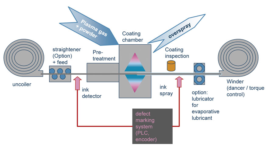
Controlled Gas Plasma Deposition (CGPD) represents an innovative method for pre-fluxing of semi-finished products. It allows the application of pure flux by means of a plasma source with comparable adhesion properties as achieved with binder-based coatings. Due to the absence of any binder or other redundant chemicals, CGPD is not limited to any drying or hardening time, opening the way for high speed flux application. This comes hand in hand with the higher environmental friendliness of a solvent and binder-free process.

Illustration of the CGPD process

Benefits of brazed aluminium HEXs in Micro Multiport (MMP) design are:
■ Cost reduction
■ Improved performance with downsizing potential
■ Weight reduction
■ Lower refrigerant charge
■ Better corrosion performance
■ Recycling advantages
Improvements in CAB:
■ Use of pre-coated components
■ Process, quality, cost
■ Binder-free CGPD coating for easy use and high speed applications

For added strength and machineability, certain alloys contain Mg. Most notably are the 6XXX series alloys (up to 1% Mg) that are used for fittings and machined components and the so-called long life brazing sheet alloys (up to 0.3% Mg in the core). There is a limit to the amount of Mg tolerated in NOCOLOK® Flux brazing. Up to 0.5% Mg can be tolerated in furnace brazing while around 1% Mg is tolerable for flame brazing.
When an Al alloy containing Mg is heated, the Mg diffuses to the surface and reacts with the surface oxide to form MgO and spinels of MgO:Al2O3. The diffusion is time-temperature dependent and is rapid above 425°C. These spinel oxides have reduced solubility in the molten flux. Furthermore, Mg and/or MgO can react with the flux forming compounds such as MgF2, KMgF3 and K2MgF4. All of these serve to poison the flux and significantly reduce its effectiveness.
In flame brazing, higher Mg concentrations can be tolerated since the faster heating rates do not allow the diffusing Mg enough time to appreciably decrease the beneficial effects of the flux. Flame brazing components containing > 1% Mg may be possible under some circumstances with increased flux loadings and very fast heating rates (<20 second braze cycle).
It should be noted that when one speaks of the brazing tolerance to Mg, it is the total sum of the Mg concentrations in both components:

[Mg] component 1 + [Mg] component 2 = [Mg] total

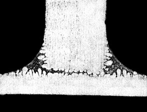
The figure below shows the effect of Mg on fillet size and geometry:

0.1% Mg

0.4% Mg

If the user is experiencing difficulties brazing and suspects elevated Mg levels as the cause, there are a couple of ways to be sure. First, check with the supplier of the alloys or perform a chemical composition analysis on the suspect alloys. This is the most certain way. Secondly, look for a golden hue on the brazed product. This is an indication that Mg alloys are being used and the color is a result of the increased oxide thickness. Furthermore, there may be a very light, almost fluffy residue on the brazed component that can literally be blown off by mouth. These visual indicators can most certainly be traced back to poor brazing results due to the presence of Mg.

Improving brazeability
There are a few ways in which the brazeability of Mg containing alloys can be improved:

  1. Increasing the flux loading. A substantial improvement is gained when increasing the flux loading up to 10 g/m2 or more in furnace brazing. In cases where there is just one component containing Mg such as in a fitting, extra flux can be brushed around the area of the joint.
  2. Increasing the heating rate. Slow heating rates allow more Mg to diffuse to the surface thereby hindering brazeability. For furnace brazing Mg containing alloys, the fastest possible heating rates achievable without sacrificing temperature uniformity will increase the tolerance to Mg.
  3. Combining increased flux loadings and faster heating rates.
  4. Maintaining proper gap tolerances and joint designs.
  5. Increasing the nitrogen flow rate to minimize furnace atmosphere contaminants that also compete to reduce brazeability.

Tip: NOCOLOK® Cs Flux

Better results are reported when using cesium containing fluxes for aluminum alloys containing Mg up to 0.6 – 0.8% Mg. Fewer leaks are observed when compared with standard flux and less porosity is noted in the joint areas. Furthermore, standard flux loads and braze cycles can be used with Cs containing fluxes.

NOCOLOK® Cs Flux is a flux of the general formula KxCsyAlFz where Cs is chemically bound. It has a melting range of 558°C – 566°C. The maximum Cs content is limited to 2% to keep the cost of the flux down. Increasing the Cs content does not increase brazeability as shown below:

Cesium reacts as a chemical buffer for Mg by forming CsMgF3 and/or Cs4Mg3F10. The flux inhibiting factors of Mg are therefore reduced.