
Welcome to the aluminium brazing blog site. We will regularly be publishing articles about aluminium brazing in this blog and we look forward to your comments, remarks and questions. Behind the scenes in this blog are the specialists for aluminium brazing from Solvay Fluor. This blog is a corporate blog and offers you new, additional ways to communicate with us.
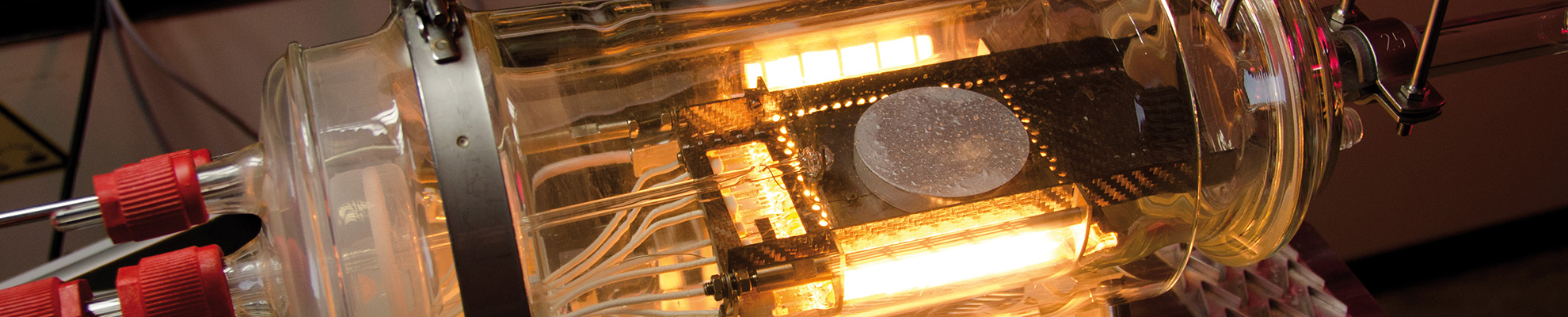
In everyday practice we can encounter problems connected with brazing imperfections – often manifested as leaking. In order to identify the failure root causes, usually a detailed examination needs to be perform. Optical metallography is one of the most important tools for such an analysis.
In everyday practice we can encounter problems connected with brazing imperfections – often manifested as leaking. In order to identify the failure root causes, usually a detailed examination needs to be perform. Optical metallography is one of the most important tools for such an analysis.
The pandemic situation these days forces us to do things in a different way and to be more innovative. Therefore, the 20th annual technical training event was organized as a Google Meet Webinar – on 2 days tailored for NAM and Asia time zones beginning of November 2020.
On October 8th & 9th, 2019 – for the 18th time since 2001 – the Aluminium Brazing Seminar took place at Solvay Fluor in Hanover (Germany). There was a ‘full house’ with 31 participants from 12 countries – representing 15 companies – plus 5 Solvay participants joining this technical training.
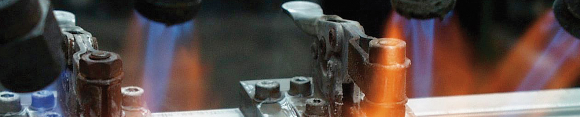
The Theory and Practice of the Flame- and Furnace-Brazing of Aluminium Dates: October 8 & 9, 2019 in Hanover/Germany Purpose of the Seminar: The language of the seminar is English. It will take place in the Conference Center and laboratories of SOLVAY GmbH, in Hanover, Germany. It will provide information concerning the manufacturing practices commonly used […]
May 7 – 8, 2019 in Düsseldorf, Germany The 6th International Congress and Exhibition on Aluminium Heat Exchanger Technologies for HVAC&R, organised by the DVS German Welding Society, will take place from May 7 – 8, 2019 in Düsseldorf/Germany in the Radisson Blu Scandinavia Hotel. Stringent environmental requirements for increasing energy efficiency and reducing emissions […]