
Welcome to the aluminium brazing blog site. We will regularly be publishing articles about aluminium brazing in this blog and we look forward to your comments, remarks and questions. Behind the scenes in this blog are the specialists for aluminium brazing from Solvay Fluor. This blog is a corporate blog and offers you new, additional ways to communicate with us.
Procedure This section describes the necessary steps and control procedures to ensure a properly brazed joint. 1. Clean the Components The joint area must be cleaned free of cutting and machining lubricants. Aqueous cleaning, solvent dipping or wiping are acceptable procedures. 2. Assemble the Components The components are assembled with the filler alloy ring in […]
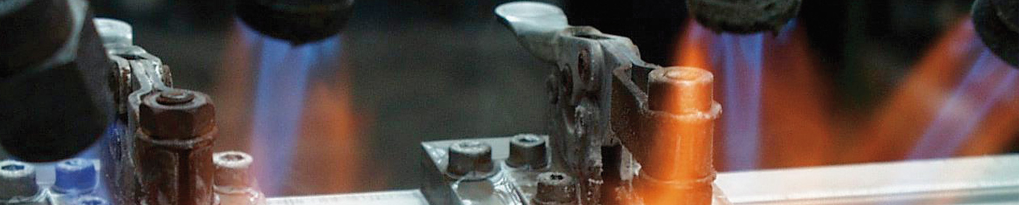
Recommended equipment for flame brazing Since the principles of flame brazing can be explained using the most basic equipment, only the equipment necessary for manual flame brazing is described. From the basic principles, all other equipment is only a matter of the degree of automation the end user wishes to achieve. Hardware Torch It is […]
Flame brazing of aluminum is not new. In fact the very first brazed aluminum assemblies were produced using a chloride based flux and a flame as the heat source. What has changed over the years is the sophistication of the types of fluxes available and to a certain extent the alloy selection. Introduction However, even […]
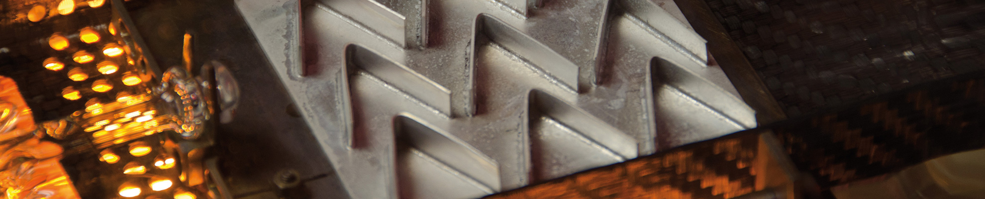
written by Leszek Orman, Radziszow / Poland; Hans-Walter Swidersky, Hannover / Germany 3 Results and discussion / Part 2 Corrosion resistance of the mock up samples was checked in the so called soaking test. Exemplary structures are shown in fig. 4: Fig. 4: Exemplary metallographic cross sections after 60 days of soaking (flux load 16g/m2, […]
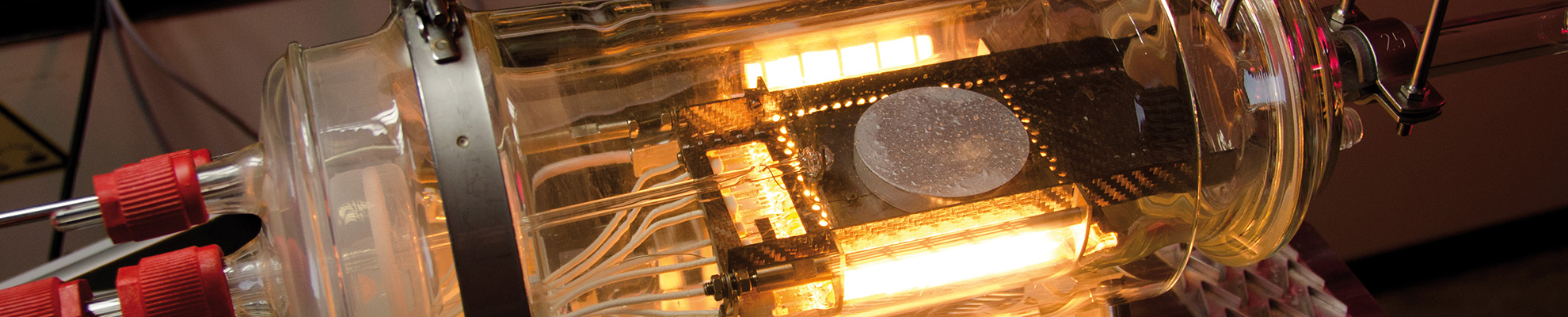
written by Leszek Orman, Radziszow / Poland; Hans-Walter Swidersky, Hannover / Germany Abstract In 2001 and in 2009 respectively, Solvay introduced two new fluxes for aluminium brazing: – NOCOLOK®Zn Flux (a ‘reactive flux’ – for the creation of precisely controlled sacrificial layers on part surfaces); and – NOCOLOK®Li Flux (for improving corrosion resistance of stationary […]
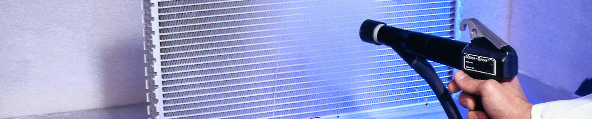
Attachment Powder Fluidity Indicator Definition of the Variables and Calculation of the Results Preliminary remark: The spraying factor Rm is a relative value for the evaluation of powders used for dry fluxing – especially when the material transport in the used equipment depends on the fluidization property of the powder. Expansion factor: Expansion factor […]
The Theory and Practice of the Flame- and Furnace-Brazing of Aluminium Dates: October 9 & 10, 2018 in Hannover/Germany Purpose of the Seminar: The language of the seminar is English. It will take place in the Conference Center and laboratories of Solvay GmbH, in Hannover, Germany. It will provide information concerning the manufacturing practices commonly used […]
The 10th International Congress and Exhibition Aluminium Brazing, organised by the DVS German Welding Society, will take place from 12 – 14 June, 2018 in Düsseldorf/Germany in the Radisson Blu Scandinavia Hotel. Leading specialists and authorities from the sector, well known experts from industry and research and other important decision makers from this field will […]