In Myths about Aluminium Brazing Fluxes Part 1 we reported about the rumor that fluxes with a lower melting range are superior. Now we take a look to another Myths about Aluminium Brazing:
Myth – A Flux with Smaller Particle Size is More “ACTIVE” and Leaves Less Flux Residue
Some rumours have been spread that a flux with a smaller particle size leads to better brazing and results in a more pleasing post-braze appearance.
But the facts are very different. It is true that a flux with a smaller particle size covers the surfaces of the work-piece more completely. Smaller flux grains will also adhere better to those surfaces, assuming that the two fluxes to be compared indeed show a difference in particle distribution.
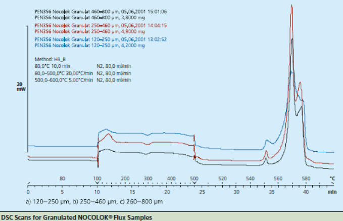
Figure 2
As particle size decreases, the total surface area of the flux increases. This allows a higher surface area of flux to be in contact with the work-piece. During heat up, there may be more efficient energy transfer to the flux with the smaller particle size. The net result is that this would affect the kinetics of melting – how quickly the flux melts – but it does not affect the melting temperature range. This is analogous to crushed ice melting quicker than a block of ice, but both melt at the same temperature. The above figure shows the melting action of various particle size fluxes using Differential Scanning Calorimetry or DSC. As expected, all particle sizes melt at precisely the same temperature.
It is also speculated that the ability of the flux to melt and spread (activity) increases as particle size decreases. In fact, the activity of the flux is related to chemistry and phase composition, not particle size. Spreading is simply a liquid phase reaction unrelated to the particle size distribution of the solid phase.
A practical example showing how flux particle size is unrelated to brazing results is comparing NOCOLOK® Flux (X50: 2 – 6µm) used for wet fluxing with NOCOLOK® Flux Drystatic (X50: 3.5 – 25µm) used for electrostatic fluxing. Heat exchangers brazed by wet fluxing can be brazed with the same results using dry fluxing, and the only difference is the particle size of the flux. The success simply depends on applying the flux uniformly.
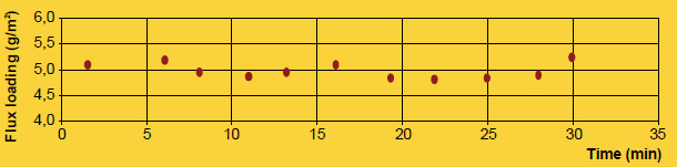
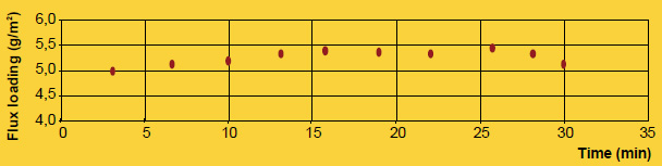
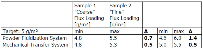
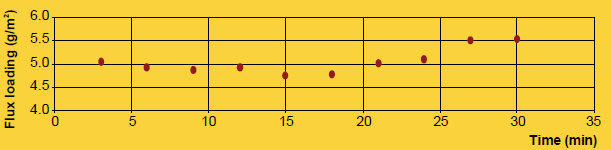
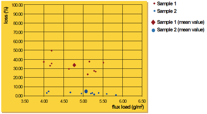
Finally, the appearance of the post-braze surface is only related to the initial flux loading, not particle size. Once the flux melts, it is completely liquid. In its molten state, the flux has no particles – neither large nor fine. Once the flux is liquid, it immediately spreads out and wets the surfaces. Upon cooling and solidification, the amount of flux residue and its distribution on the surface of the work-piece is related entirely to the initial flux loading, and not particle size.
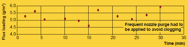
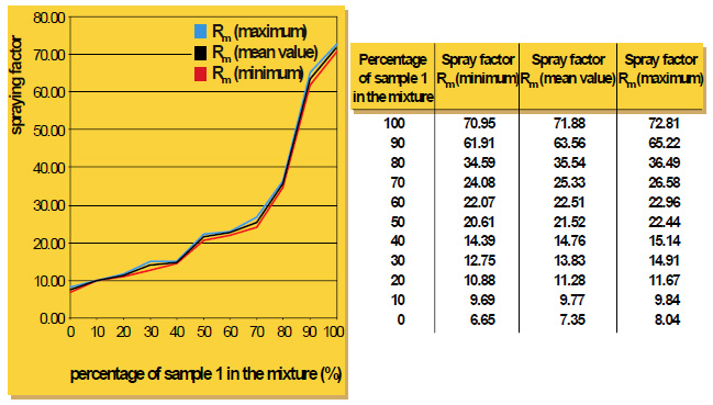
It is true that particle size distribution of a flux affects slurry characteristics. A finer powder will stay longer suspended (i.e. it settles slower) than a coarser product. Material with larger grains seems to build-up more rapidly on inside surfaces of slurry tanks and spraying equipment. Regardless of the specific particle distribution of a flux, continuous agitation is necessary to prevent settling and build-up. Regular maintenance is the only way to avoid the formation of solidified material residues.
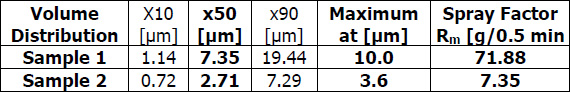
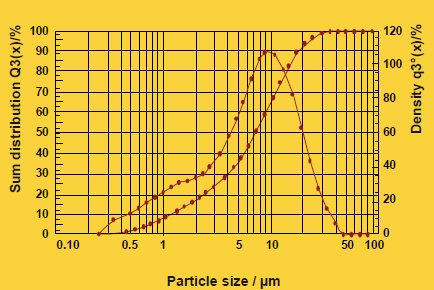
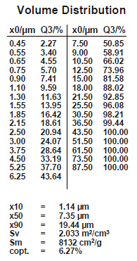
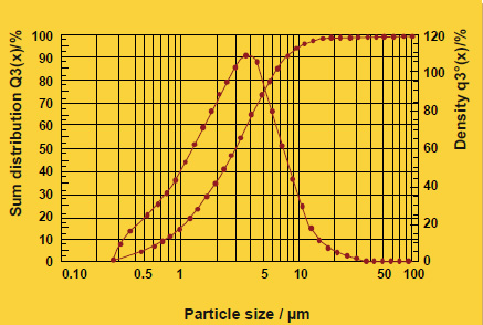
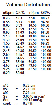
A realistic comparison of particle size distribution can only be done by measuring samples on the same equipment under exactly the same conditions.
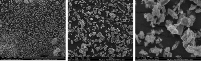
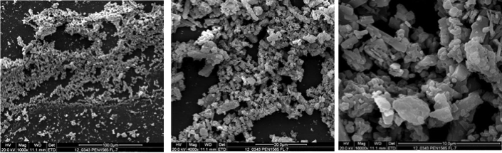
Furthermore, we have electron microscope comparison pictures of several flux powders – showing that the grain morphology is quite similar in all products.
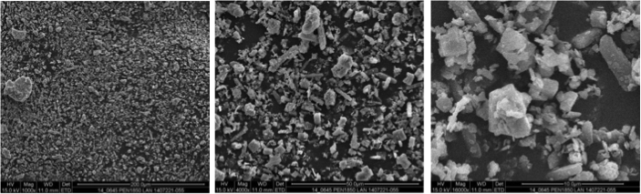
SEM Picture NOCOLOK© Flux Quzhou 1,000/4,000/16,000
SEM Picture NOCOLOK© Flux Bad Wimpfen 1,000/4,000/16,000
SEM Picture Competitor 1 1,000/4,000/16,000
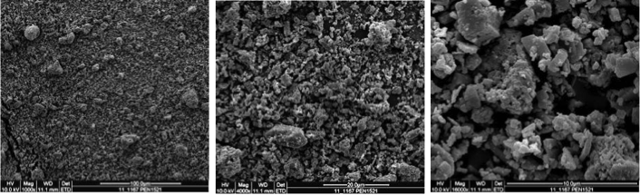
SEM Picture Competitor 2 1,000/4,000/16,000